Ssm mapping configuration example, Network requirements, Network diagram – H3C Technologies H3C S7500E Series Switches User Manual
Page 132: Configuration procedure

5-25
IGMP is enabled
Current IGMP version is 2
Value of query interval for IGMP(in seconds): 60
Value of other querier present interval for IGMP(in seconds): 125
Value of maximum query response time for IGMP(in seconds): 10
Querier for IGMP: 10.110.2.1 (this router)
Total 1 IGMP Group reported
SSM Mapping Configuration Example
Network requirements
z
The PIM-SM domain applies both the ASM model and SSM model for multicast delivery.
Switch D’s VLAN-interface 104 serves as the C-BSR and C-RP. The SSM group range is
232.1.1.0/24.
z
IGMPv3 runs on Switch D’s VLAN-interface 400. The receiver host runs IGMPv2, and does
not support IGMPv3. Therefore, the Receiver host cannot specify expected multicast
sources in its membership reports.
z
Source 1, Source 2, and Source 3 send multicast packets to multicast groups in the SSM
group range. It is required to configure the IGMP SSM mapping feature on Switch D so that
the receiver host will receive multicast data from Source 1 and Source 3 only.
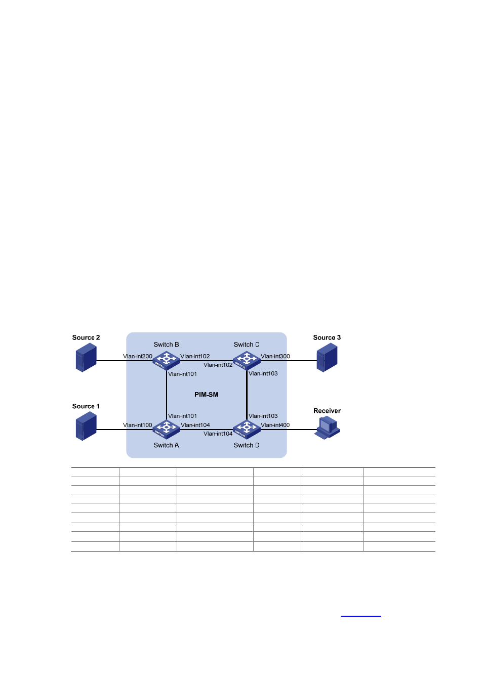
Network diagram
Figure 5-6 Network diagram for IGMP SSM mapping configuration
Device
Interface
IP address
Device
Interface
IP address
Source 1
—
133.133.1.1/24
Source 3
—
133.133.3.1/24
Source 2
—
133.133.2.1/24
Receiver —
133.133.4.1/24
Switch A
Vlan-int100
133.133.1.2/24
Switch C
Vlan-int300
133.133.3.2/24
Vlan-int101
192.168.1.1/24
Vlan-int103
192.168.3.1/24
Vlan-int104
192.168.4.2/24
Vlan-int102
192.168.2.2/24
Switch B
Vlan-int200
133.133.2.2/24
Switch D
Vlan-int400
133.133.4.2/24
Vlan-int101
192.168.1.2/24
Vlan-int103
192.168.3.2/24
Vlan-int102
192.168.2.1/24
Vlan-int104
192.168.4.1/24
Configuration procedure
1) Configure IP addresses and unicast routing
Configure the IP address and subnet mask of each interface as per
. The detailed
configuration steps are omitted here.
