Delta Electronics VFD-M User Manual
Page 95
Chapter 4 Parameters|
4-60
Revision May 2008, ME14, SW V3.04
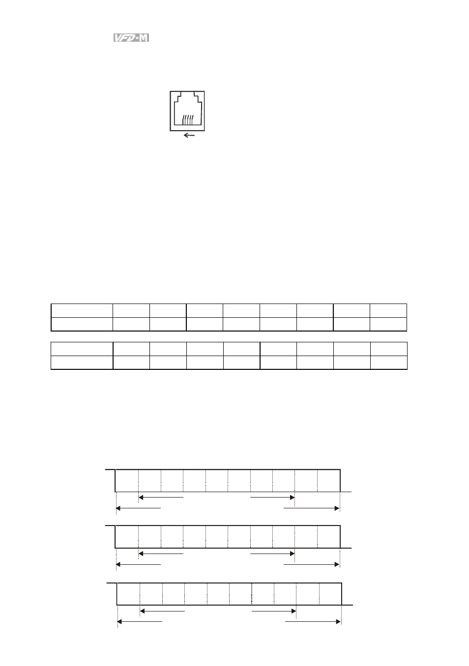
Each drive has a built-in RS-485 serial interface, marked (RJ-11 Jack) on the control terminal
block, whose pins are defined as shown:
6
1
1: +15V
2: GND
3: SG-
4: SG+
5: NC
6: for communication
Either ASCII or RTU Modbus protocols are used for communication. Users can select the
desired mode along through parameters Pr.92 and Pr.113.
Each VFD-M AC drive has a pre-assigned communication address specified by Pr.88. The
master controller communicates with each AC drive according to its particular address.
Code
Meaning:
ASCII mode:
Each 8-bit data is the combination of two ASCII characters. For example, a 1-byte data: 64 Hex,
shown as ‘64’ in ASCII, consists of ‘6’ (36Hex) and ‘4’ (34Hex).
Character ‘0’ ‘1’ ‘2’ ‘3’ ‘4’ ‘5’ ‘6’ ‘7’
ASCII code
30H
31H
32H
33H
34H
35H
36H
37H
Character ‘8’ ‘9’ ‘A’ ‘B’ ‘C’ ‘D’ ‘E’ ‘F’
ASCII
code 38H 39H
41H
42H
43H 44H
45H
46H
RTU mode:
Each 8-bit data is the combination of two 4-bit hexadecimal characters. For example, 64 Hex.
2. Data Format
2.1 10-bit character frame (For 7-bit character):
( 7.N.2 : Pr.92=0)
( 7.E.1: Pr.92=1)
Start
bit
0
1
2
3
4
5
6
Stop
bit
10-bit character frame
( 7.O.1:Pr.92=2)
Odd
parity
Start
bit
0
1
2
3
4
5
6
Stop
bit
10-bit character frame
Even
parity
Start
bit
0
1
2
3
4
5
6
Stop
bit
7-bit character
10-bit character frame
Stop
bit
7-bit character
7-bit character