Delta Electronics VFD-M User Manual
Page 112
Chapter 4 Parameters|
Revision May 2008, ME14, SW V3.04
4-77
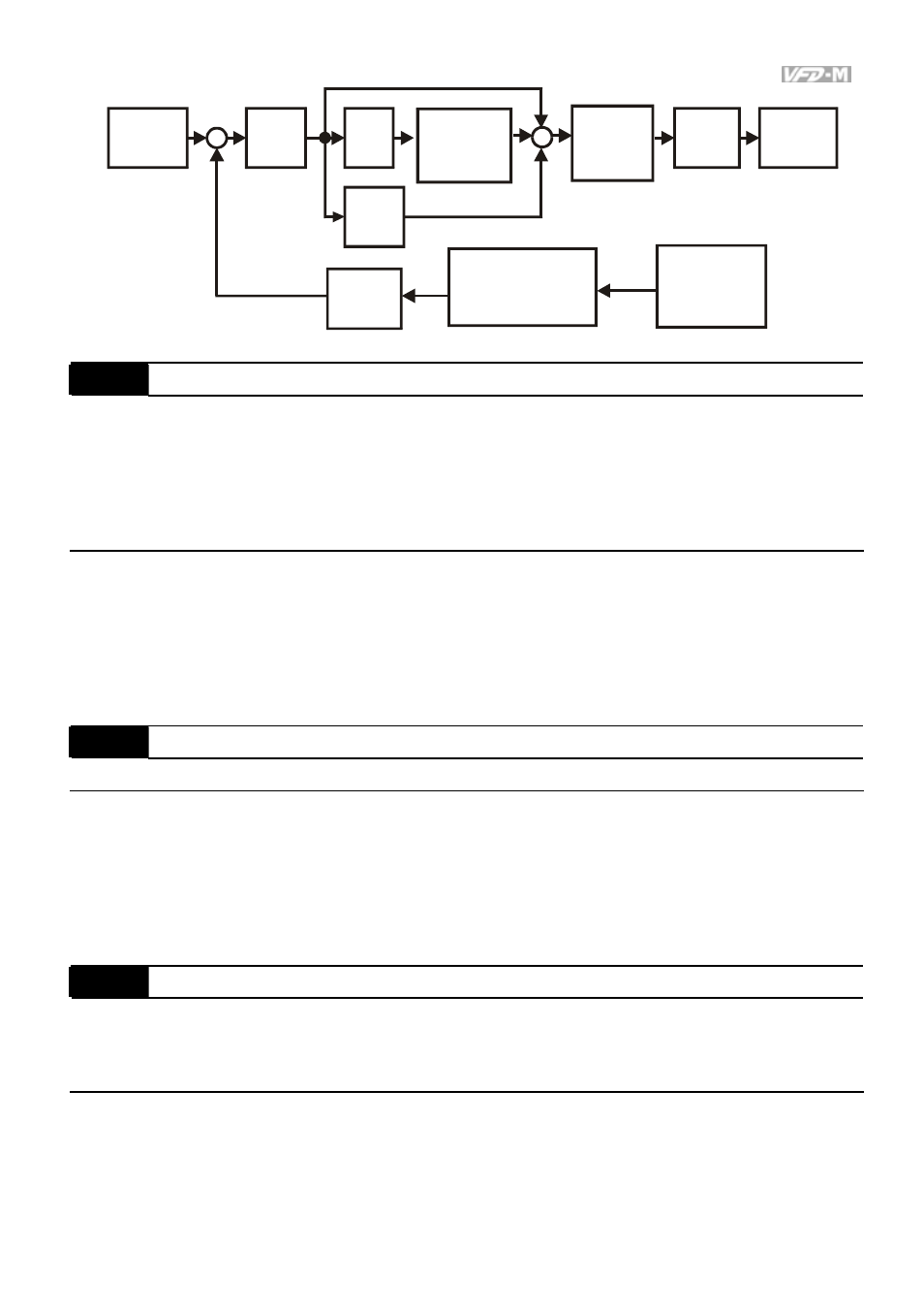
P
Pr.117
I
Pr.118
D
Pr.119
Pr.120
AVI(
)
ACI(
)
Pr.128~Pr.130
Pr.131~Pr.133
Pr.116
+
-
+
+
Pr.135
LPF
Targeted
value
Upper Bound
of Integral
Value
Pr.122
+
Limit of PID
Output
Frequency
One Time
Delay
Pr.121
Definition of
Detection Value
Frequency
Command
Selection of
Detection value
Pr. 116
PID Feedback Terminal Selection
Factory Setting: 00
Settings 00 Input positive PID feedback, PV from AVI (0 to 10V)
01 Input negative PID feedback, PV from AVI (0 to 10V)
02 Input positive PID feedback, PV from ACI (4 to 20mA)
03 Input negative PID feedback, PV from ACI (4 to 20mA)
Select an input terminal to be the PID feedback. Please verify the PID feedback position is
different from the Frequency Set Point position.
Negative feedback = positive targeted value – detective value. Positive feedback = negative
targeted value + detective value.
Pr. 117
Proportional Gain (P)
Settings 0.0 to 10.0
Factory Setting: 1.0
This parameter determines the feedback loop Gain. If the gain is large, the response will be
strong and immediate (If the gain is too large, vibration may occur). If the gain is small, the
response will be weak and slow.
When I=0.0 and D=0.0, it is only used for proportional control.
Pr. 118
Integral Time (I)
Unit: 0.01sec
Factory Setting: 1.00
Settings 0.01 to 100.00 sec
0.00
disable
This parameter determines the speed of response for the PID feedback loop. If the integral
time is long, the response will be slow. If the integral time is short, the response will be quick.
Be careful not to set (I) too small, since a rapid response may cause oscillation in the PID loop.