Delta Electronics VFD-M User Manual
Page 83
Chapter 4 Parameters|
4-48
Revision May 2008, ME14, SW V3.04
This parameter can be used to compensate motor slip. Although no linear, it typically adds 6Hz
for a setting of 10 if Pr.03=60 Hz. When the output current of the AC drive is greater than the
motor no-load current (Pr.53), the AC drive will adjust its output frequency according to this
parameter.
Pr.56
Reserved
Pr.57
Rated Current Display of the AC motor drive
Settings Read Only
Factory Setting: ##.#
Pr.57 displays the rated current of the AC motor drive. By reading this parameter the user can
check if the AC motor drive is correct. See Pr.80 for details.
Pr.58
Electronic Thermal Overload Relay Selection
Factory Setting: 02
Settings 00 Standard Motor (self cool motor)
01 Inverter Motor (auxiliary cool fan on motor)
02
Inactive
This function is used to limit the output power of the AC drive when powering a “self-cooled
motor” at low speed.
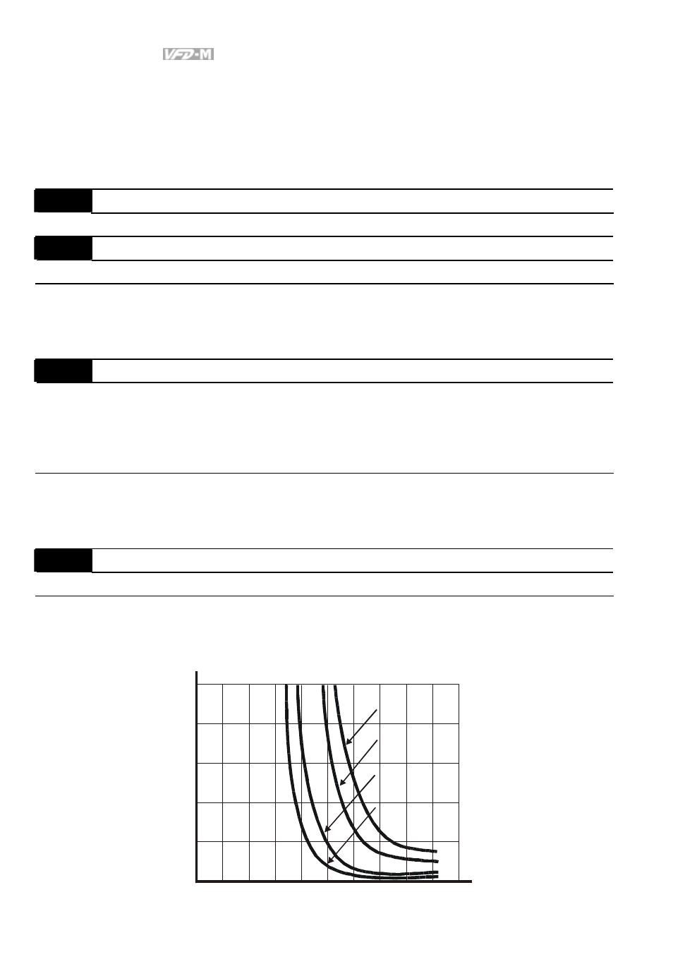
Pr.59
Electronic Thermal Motor Overload
Unit: 1 second
Settings 30 to 300sec
Factory Setting: 60
The parameter determines the time required to activate the I
2
t electronic thermal motor
overload protection. The graph below shows I
2
t curves at 150% output power for 1 minute.
1
2
3
4
5
60Hz or more
50Hz
10Hz
5Hz
0
20 40 60 80 100 120 140 160 180 200
Operation
time(min)
Load
factor
(%)