Delta Electronics VFD-M User Manual
Page 147
Appendix B Accessories|
B-2
Revision May 2008, ME14, SW V3.04
NOTE
1.
Please select the brake unit and/or brake resistor according to the table. “-“ means no
Delta product. Please use the brake unit according to the Equivalent Resistor Value.
2.
If damage to the drive or other equipment is due to the fact that the brake resistors and
the brake modules in use are not provided by Delta, the warranty will be void.
3.
Take into consideration the safety of the environment when installing the brake resistors.
4.
If the minimum resistance value is to be utilized, consult local dealers for the calculation of
the power in Watt.
5.
Please select thermal relay trip contact to prevent resistor over load. Use the contact to
switch power off to the AC motor drive!
6.
When using more than 2 brake units, equivalent resistor value of parallel brake unit can’t
be less than the value in the column “Minimum Equivalent Resistor Value for Each AC
Drive” (the right-most column in the table).
7.
Please read the wiring information in the user manual of the brake unit thoroughly prior to
installation and operation.
8.
In applications with brake resistor or brake unit, Pr.25 (Over-voltage stall prevention) must
be disabled. And Pr.102 (AVR function) shall not be used.
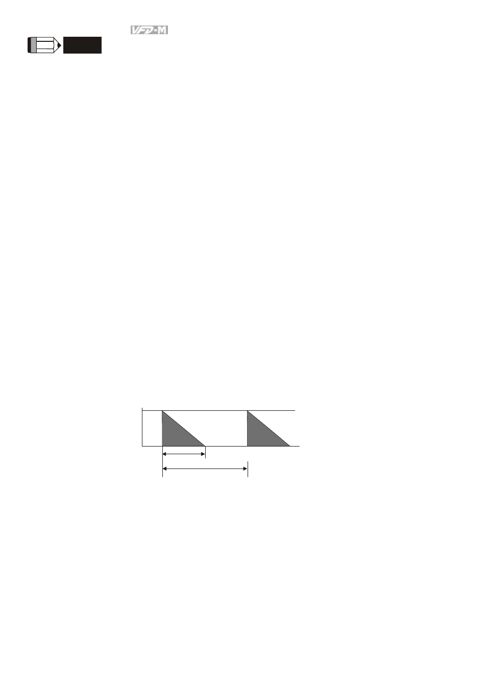
9.
Definition for Braking Usage ED%
Explanation: The definition of the barking usage ED(%) is for assurance of enough time
for the brake unit and brake resistor to dissipate away heat generated by braking. When
the brake resistor heats up, the resistance would increase with temperature, and braking
torque would decrease accordingly. Suggest cycle time is one minute
100%
T0
T1
Braking Time
Cycle Time
ED% = T1/T0x100(%)
10. For safety reasons, install a thermal overload relay between brake unit and brake resistor.
Together with the magnetic contactor (MC) in the mains supply circuit to the drive it offers
protection in case of any malfunctioning. The purpose of installing the thermal overload
relay is to protect the brake resistor against damage due to frequent braking or in case
the brake unit is continuously on due to unusual high input voltage. Under these
circumstances the thermal overload relay switches off the power to the drive. Never let
the thermal overload relay switch off only the brake resistor as this will cause serious
damage to the AC Motor Drive.