1 basic wiring diagram, 1 basic wiring diagram -2, Im 3 – Delta Electronics VFD-M User Manual
Page 19: Danger
Chapter 2 Installation and Wiring|
2-2
Revision May 2008, ME14, SW V3.04
DANGER!
1.
A charge may still remain in the DC bus capacitors with hazardous voltages even if the power
has been turned off. To prevent personal injury, please ensure that the power is turned off and
wait ten minutes for the capacitors to discharge to safe voltage levels before opening the AC
motor drive.
2.
Only qualified personnel familiar with AC motor drives is allowed to perform installation, wiring
and commissioning.
3.
Make sure that the power is off before doing any wiring to prevent electric shock.
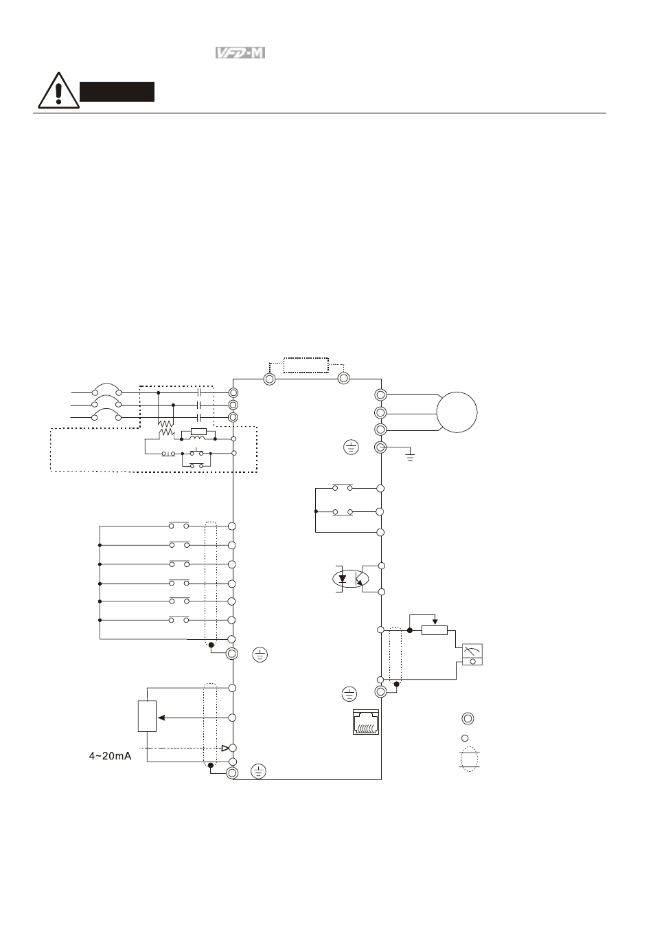
2.1 Basic Wiring Diagram
Users must connect wires according to the following circuit diagram shown below.
B2
U/T1
V/T2
W/T3
IM
3~
MO1
MCM
RS-485
NOTE: Do not plug a Modem or telephone line to the RS-485 communication
port, permanent damage may result. Terminal 1& 2 are the power
sources for the optional copy keypad and should not be used while
using RS-485 communication.
6←1
B1
E
RA
RB
RC
120VAC/250VAC 5A
24VDC less than 2.5A
M0
M1
M2
M3
M4
M5
GND
AVI
GND
+10V 10mA(MAX)
3
2
1
VR
0~10VDC
VR:3K~5KΩ
AFM
GND
+
-
VR(1KΩ)
DC 0~10V
RJ-11
1:15V
2:GND
3:SG-
4:SG+
5:Reserved
6:Reserved
Brake Resistor (optional)
Main Circuit Power
The spec. of main circuit
terminal is M3.0
Factory default
Forward/Stop
Reverse/Stop
Reset
Multi-step 1
Multi-step 2
Multi-step 3
Common signal
Master Frequency setting
factory default is VR which is
on the digital keypad
Analog voltage
Analog current
Power for speed setting
series interface
AC Motor
Grounding
Multi-function indication
output contact
Factory default:
indicates malfunction
Multi-function Photocoupler
output contact 48VDC 50mA
Factory default: Indicates
during operation
Analog output
Factory default:
output frequency
For adjustment
Main circuit (power)
terminals
Control circuit terminals
Shielded leads
* If it is single phase model, please select any of the two input power
terminals in main circuit power.
* Single phase model can be input 3-phase power.
S/L2
T/L3
NFB
R/L1
S/L2
T/L3
SA
OFF
ON
MC
MC
RB
RC
Recommended Circuit
when power supply
is turned OFF by a
fault output
R/L1
ACI
E
E
E