Chapter 3 keypad and start up, 1 keypad, 1 description of the digital keypad – Delta Electronics VFD-M User Manual
Page 30: Chapter 3 keypad and start up -1, 1 keypad -1, 1 description of the digital keypad -1, Vfd-m, 1 keypad 3.1.1 description of the digital keypad
Revision May 2008, ME14, SW V3.04
3-1
Chapter 3 Keypad and Start Up
3.1 Keypad
3.1.1 Description of the Digital Keypad
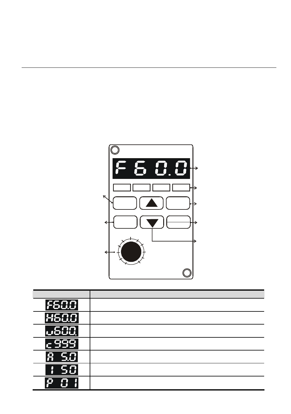
The digital keypad includes two parts: Display panel and keypad. The display panel provides the
parameter display and shows the operation status of the AC drive and the keypad provides
programming and control interface.
DIGITAL KEYPAD
RUN
STOP FWD
REV
MODE
RUN
ENTER
STOP
RESET
0
50
100
FREQ SET
LC-M02E
VFD-M
Program/Function mode key
Selects normal mode/
program mode. Displays
the AC drive status, such as
output freq., selects the
parameters.
Enter Key
Press ENTER after
key in the elected
parameters or
change data.
Potentiometer
For master Frequency
setting refer to Pr.00.
LED Display
Indicates motor and
drive parameter.
LED Indicates
Lamp lights during RUN,
STOP, FWD & REV
operation.
Run key
Starts AC drive operation.
STOP/RESET Key
Stops and resets the
parameter after a fault
occurs.
UP and DOWN Key
Sets the parameter number
or changes the numerical
data such as the freq.
reference.
Displayed Message
Descriptions
The AC drives Master Frequency.
The Actual Operation Frequency present at terminals U, V, and W.
The custom unit (v), where v = H x Pr.65.
The counter value (c).
The output current present at terminals U, V, and W
The internal PLC process step currently being performed.
The specified parameter.