Delta Electronics VFD-M User Manual
Page 28
Chapter 2 Installation and Wiring|
Revision May 2008, ME14, SW V3.04
2-11
Terminal
Symbol
Terminal Function
Factory Settings (NPN mode)
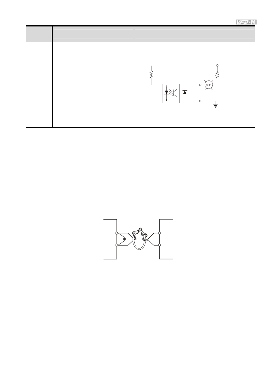
MO1
Multi-function Output Terminal
(Photocoupler)
Maximum: 48Vdc, 50mA
Refer to P45 for programming.
MO1-DCM
MO1
MCM
Internal Circuit
Max: 48Vdc/50mA
MCM
Multi-function Output Common
(Photocoupler)
Common for Multi-function Outputs
Note: Use twisted-shielded, twisted-pair or shielded-lead wires for the control signal wiring. It is
recommended to run all signal wiring in a separate steel conduit. The shield wire should only be
connected at the drive. Do not connect shield wire on both ends.
Analog inputs (AVI, ACI)
Analog input signals are easily affected by external noise. Use shielded wiring and keep it as
short as possible (<20m) with proper grounding. If the noise is inductive, connecting the shield
to terminal GND can bring improvement.
If the analog input signals are affected by noise from the AC motor drive, please connect a
capacitor (0.1
μ
F and above) and ferrite core as indicated in the following diagrams:
C
AVI/ACI
GND
ferrite core
wind each wires 3 times or more around the core
Digital inputs (M0~M5)
When using contacts or switches to control the digital inputs, please use high quality
components to avoid contact bounce.
Digital outputs (MO1)
Make sure to connect the digital outputs to the right polarity, see wiring diagrams.
When connecting a relay to the digital outputs, connect a surge absorber or fly-back diode
across the coil and check the polarity.