Parallel connector, 2 − names and functions of parts – Teac HS-4000 User Manual
Page 14
14
TASCAM HS-4000
2 − Names and functions of parts
color display might flicker or noise might be heard when
monitoring.
If this occurs, use the GROUND terminal. (Please prepare a
wire to use with the GROUND terminal.)
PARALLEL connector
The PARALLEL connector on the rear panel allows external
control of this unit.
The pin assignments are as follows.
Pin
No.
Timeline / Take /
Playlist [Single] /
On Air
Playlist [Dual, A/B
MIXED]
TASCAM
RC-SS20
PonMode
I/O
1 GND
GND
GND
2 PLAY
PLAY A
FLASH 1
I
3 STOP
STOP A
FLASH 2
I
4 RECORD
(Reserved)
FLASH 3
I
5 SKIP FWD
SKIP FWD
FLASH 4
I
6 SKIP BWD
SKIP BWD
FLASH 5
I
7 (Reserved)
STOP B
STOP
I
8 FADER START
FADER_START A
FADER_START
I
9 TALLY_BC_STOP TALLY_PAUSE B
TALLY_BC_STOP O
10
TALLY_PAUSE
/ TALLY_BC_
PAUSE
TALLY_PAUSE A
TALLY_PAUSE
A / TALLY_BC_
PAUSE
O
11 TALLY_RECORD (Reserved)
RESERVED
O
12 TALLY_STOP
TALLY_STOP A
TALLY_STOP
O
13 TALLY_PLAY
TALLY_PLAY A
TALLY_PLAY
O
14
REMOTE_
SELECT,
H or Open
REMOTE_SELECT,
H or Open
REMOTE_
SELECT, L
I
15 PAUSE
PAUSE
FLASH 6
I
16 (Reserved)
PLAY B
FLASH 7
I
17 AUX1, FF
AUX1, FF
FLASH 8
I
18 AUX2, REW
AUX2, REW
FLASH 9
I
19 AUX3, MARK
AUX3, MARK
FLASH 10
I
20 (Reserved)
A/B SELECT
FLASH_PAGE
I
21 TALLY_BC_
STANDBY
TALLY_PLAY B
TALLY_BC_
STANDBY
O
22 TALLY_CF1 /
TALLY_BC_CM TALLY_STOP B
TALLY_CF1 /
TALLY_BC_CM
*1
O
23 TALLY_ONLIN
TALLY_ONLINE A TALLY_ONLINE
O
24 TALLY_CF2 /
TALLY_BC_END TALLY_ONLINE B
TALLY_CF2 /
TALLY_BC_END
*2
O
25 +5V *3
+5V *3
+5V *3
I: Command input for transport control
Internal circuit, +5V pull-up
Operates with low commands of 50 msec or more
O: Command output, for tally output
The internal circuit is open collector (10Ω output
impedance)
Low command output when operating
20 V dielectric strength, 35 mA maximum current
*1: With an RC-SS20, this is assigned to the CF.
*2: With an RC-SS20, this is assigned to the CD indicator.
*3: 50 mA maximum supplied current
When REMOTE Select (pin 14) is set to high, it functions
according to the operation mode and can be used as an
ordinary parallel controller.
When set to low, flash start mode is enabled. In addition,
depending on the high/low setting of the Flash Page (pin 20),
the key assignments are as follows.
Pin 14
Pin 20
Flash start take
Low
High
1-10
Low
Low
11-20
tally_BC_xxx: Use the menu setting to turn output ON or OFF.
(When connected to a TASCAM RC-SS20, set output to OFF.)
tally_BC_STOP/CM/END: 250msec pulse output
tally_BC_STANDBY/PAUSE: level output
When this unit is set to dual or A/B MIXED playlist mode and
REMOTE Select (pin 14) is set to high (dual or A/B MIXED
Playlist), use pin 20 (A/B SELECT) to select player A/B (Hi is player
A, Lo is player B).
The following pins affect the selected player.
Pin 5
SKIP FWD
Pin 6
SKIP BWD
Pin 15
PAUSE
Pin 17
AUX1
Pin 18
AUX2
Pin 19
AUX3
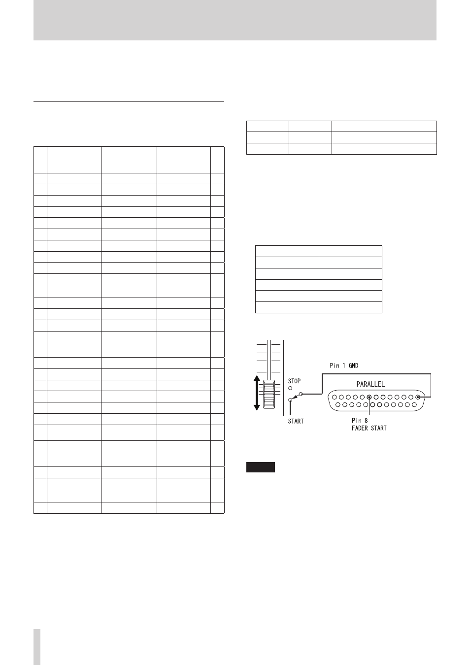
The following example is of a connection that uses a fader to
start and stop playback of this device.
For details about the AUX 1-3 (pins 17-19) function assignments,
see“PARALLEL page” on page 107.
NOTE
When controlling this unit with an external device that
is connected to the PARALLEL connector, by simultane-
ously inputting PLAY and RECORD signals while this unit is
stopped, you can start recording immediately. In addition,
by simultaneously inputting PLAY and RECORD signals
during playback in timeline mode, you can start overwriting
the recording.