Islander (satellite reader) – Gasboy CFN Series SCII Start-Up Manual User Manual
Page 78
CFN Series System
9-6
03/07/03
ISLANDER (SATELLITE READER)
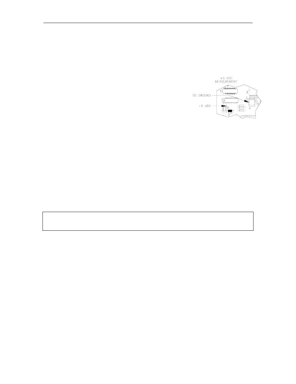
+5 VDC Measurement
1.
Loosen and remove the two wing nuts that hold the hood on the head of the unit. Remove
the four screws from the outside of the hood. Lift hood straight up and remove it.
2.
For C05375 board: Measure the +5 VDC between the top of
the resistor R7 (+) and the case of crystal Y1 (-). The
voltage should be +5.00 to +5.10 VDC. If the voltage does
not fall within this range, adjustment is necessary. Follow
the steps below to adjust the supply. If the voltage is within
tolerance, skip to Step 11.
For C05857 board: Measure the +5 VDC between the test
points TP1 (5V) and TP2 (Gnd). The voltage should be
+5.00 to +5.10 VDC. If the voltage does not fall within this
range, adjustment is necessary. Follow the steps below to
adjust the supply. If the voltage is within tolerance, skip to
Step 11.
+5 VDC Adjustment
3.
Turn off the AC POWER switch in the island card reader.
4.
Remove the three screws that hold the power supply cover onto the supply. Remove the
cover.
5.
For board C05375: Attach the meter probes to R7 and Y1 on the CPU PCB.
For board C05857: Attach the meter probes to TP1 and TP2 on the CPU PCB.
6.
Turn the AC POWER switch back on.
CAUTION
Be careful not to touch anything but the adjustment screw. High voltage exists at
various points on the supply and the circuit mounted on the rear of the supply.
7.
Using a 1/8 inch or smaller plastic, flat blade screwdriver, adjust the power supply to +5 VDC
by turning the screw clockwise to increase voltage, counterclockwise to decrease voltage.
Turn the screw slightly to judge how sensitive the adjustment is.
8.
Disconnect the meter probes.
9.
Turn the AC POWER switch off and return the power supply cover to its normal location.
10. Turn the AC POWER switch back on.
+12 VDC Measurement
11. Measure the +12 VDC between the red (+) and black (-) wires on the DC output connector of
the power supply. The voltage should be +11.00 to +14.00 VDC.
NOTE: This voltage is used only for receipt printers and is not adjustable. If there is no
receipt printer, no red and black wires will be present on the DC output connector.
12. Replace the cover, hood, and screws.