Gasboy CFN Series SCII Start-Up Manual User Manual
Page 46
CFN Series System
5-8
03/07/03
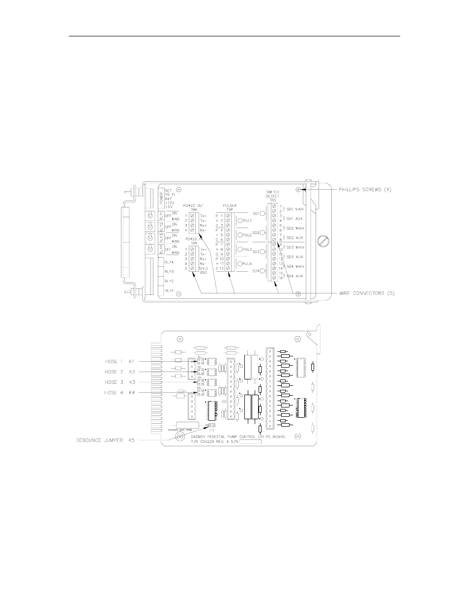
Pump Control I/O PCB
The Pump Control I/O PCB, shown below, consists of two parts: the PCB itself and a cover plate.
In order to set the jumpers and switches on the I/O PCB, you must remove all the connectors and
the cover plate.
1.
Remove the five green connectors from the front of the Pump Control I/O board. Remove
the board from the card cage in the same manner as the EXPMUX Pump Control CPU
board.
2.
Remove the four Phillips screws securing the cover plate to the PCB and remove the cover
plate.
Figure 5-3. Pump Control I/O Cover Plate and PCB
This manual is related to the following products: