Islander – Gasboy CFN Series SCII Start-Up Manual User Manual
Page 75
DC Power
03/07/03
9-3
ISLANDER
+5 VDC Measurement
1.
Unlock and open rear door on head of unit.
2.
On the CPU PCB, measure at the Vcc and Vss test points, with the positive (+) probe on Vcc
and the negative (-) probe on Vss. The voltage should be +5.00 to +5.10 VDC. If the voltage
does not fall within this range, adjustment is necessary. Follow the steps below to adjust the
supply. If the voltage is within tolerance, skip to step 11.
+5 VDC Adjustment
3.
Turn off the power to the Islander II. Loosen and remove the two wing nuts that hold the
hood on the head of the unit. Remove the four screws from the outside of the hood. Lift
hood straight up to remove.
4.
Remove the three screws that hold the power supply cover onto the supply. Remove the
cover.
5.
Attach the meter probes to Vcc and Vss on the CPU PCB.
6.
Turn the AC POWER switch back on.
CAUTION
Be careful not to touch anything but the adjustment screw. High voltage exists at
various points on the supply.
7.
Using a 1/8 inch or smaller plastic, flat-blade screwdriver, adjust the power supply to +5 VDC
by turning the screw clockwise to increase voltage, counterclockwise to decrease voltage.
Turn the screw slightly to judge how sensitive the adjustment is.
8.
Disconnect the meter probes.
9.
Turn the AC POWER switch off and return the power supply cover to its normal location.
10. Turn the AC POWER switch back on.
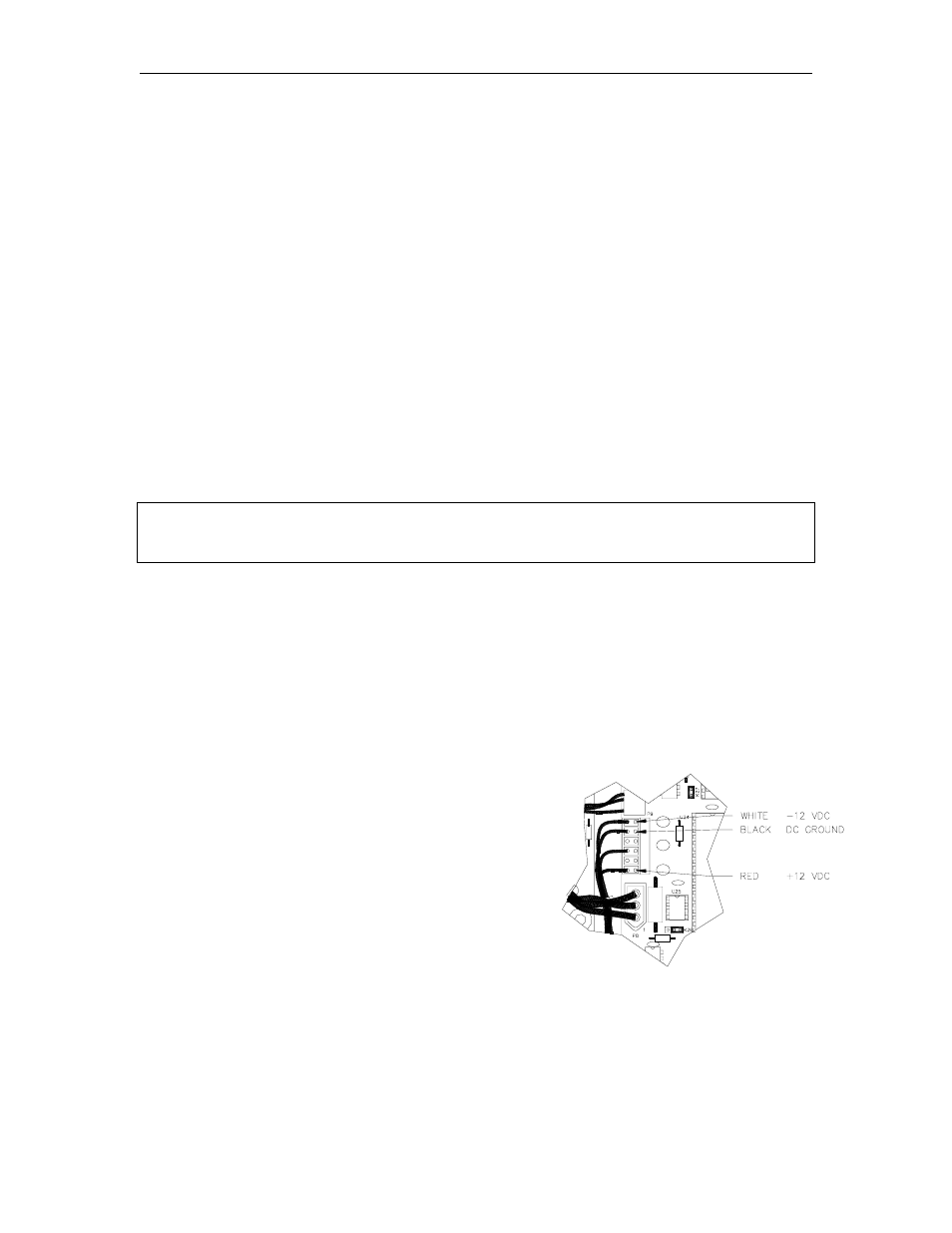
+12 VDC Measurement
11. Locate the DC power input connector (P9) on
the CPU PCB. Measure the +12 VDC between
the red (+) and black (gnd) wires on the DC
input power connector of the CPU PCB. The
voltage should be +11.00 to +14.00 VDC.
NOTE: This voltage is not adjustable.
-12 VDC Measurement
12. On the P9 connector, measure the -12 VDC
between the white (-) and black (gnd) wires on
the DC input power connector of the CPU PCB.
Voltage should be -11.00 to -14.00 VDC.
NOTE: This voltage is not adjustable.
13.
Replace the cover, hood, and screws.