Standalone star printer, Pumps and dispensers – Gasboy CFN Series SCII Start-Up Manual User Manual
Page 54
CFN Series System
5-16
03/07/03
Switch SW1 (continued)
FPR Address
Switch 3
Switch 4
1
OFF
OFF
2
OFF
ON
3
ON
OFF
4
ON
ON
STANDALONE STAR PRINTER
The switches on the standalone Star printer are set at the factory and should be correct. If
change is needed, refer to the CFN Diagnostic Manual for details.
PUMPS AND DISPENSERS
If you are using GASBOY Series 9800 pumps and dispensers, there are switches that must be set
correctly to insure proper operation of your CFN system. See the Series 9800
Installation/Operation Manual for details.
If you are using Tokheim DPT's or another pump interface (Gilbarco, Wayne, etc.) refer to the
Pump Interface Manual, C09146 for assistance.
Cabling and Port Jumper Configuration for Tokheim Pumps
1.
The Tokheim Splitter is required to establish an electronic interface between the Islander II
and any Tokheim electronic pumps/remote dispensers. The Tokheim splitter is connected to
either port 1 (TB5) or 3 (TB6) of the Islander II with either a C05756 25 pin D-type connector
(female) or a C07262 Gasboy ISL/TOK termination box (See Islander II Installation Manual,
C35963 for cabling diagrams). The maximum distance, including all cables, from the
Islander II to the Tokheim 67 interface box is 250 feet. The C05756 connector can accept up
to a maximum of 22 AWG wire. The C07262 termination box will accept up to 18 AWG wire.
All RS-232 requirements defined in the Islander II Installation Manual apply.
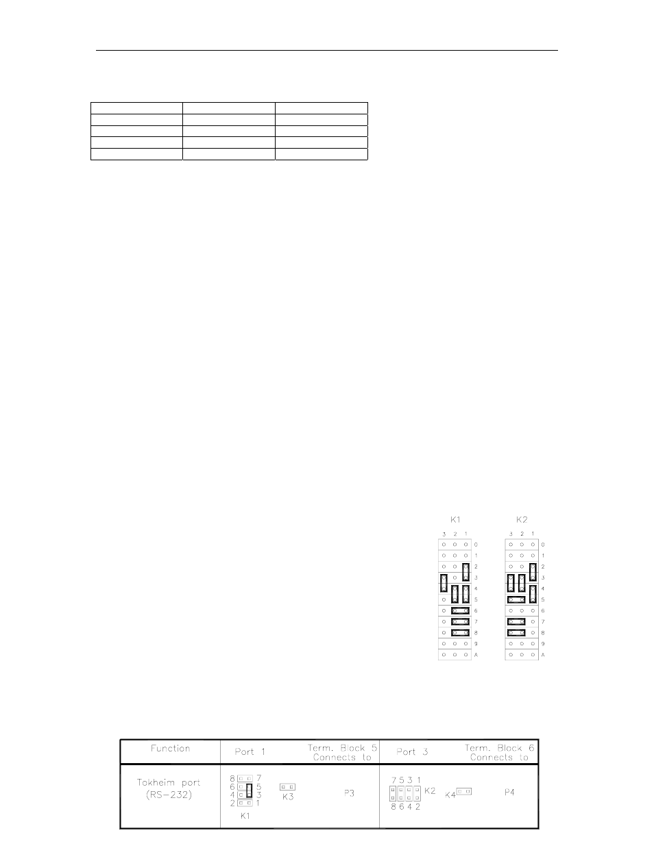
2.
The SC II CPU K1 (port1) or K2 (port 3) jumper patch must be
configured as follows to communicate with the Tokheim pumps.
The jumpers on the Site Communication I/O board in the head of the Islander (on the inside
of the left partition) for port 1 or port 3 must be configured as shown below: