Pump control unit(s) – Gasboy CFN Series SCII Start-Up Manual User Manual
Page 76
CFN Series System
9-4
03/07/03
PUMP CONTROL UNIT(S)
+5 VDC Measurement
1.
Turn off the AC and DC power switches on the supply assembly.
2.
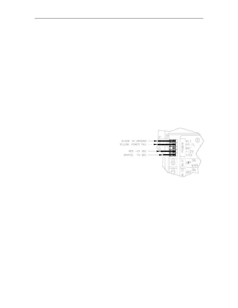
Locate the connector labeled POWER in the upper left-hand corner of the motherboard.
Remove the black plastic cover.
3.
Turn on the AC and DC power switches.
4.
Measure the +5 VDC between the orange (+) and black (-) wires. The voltage should be
+4.95 to +5.05 VDC.
5.
Measure the +12 VDC between the red (+) and black (-) wires. The voltage should be
+11.50 to +15.50 VDC depending on the type and number of pulsers and the number of
relays energized.
6.
Measure the POWER FAIL between the yellow (+) and black (-) wires. The voltage should
be +4.75 to +5.05 VDC.
NOTE:
There are no adjustments for these voltages.
7.
Turn off the AC and DC power switches.
8.
Replace the black plastic cover on the
connector and turn the AC and DC
power switches back on.