Gasboy CFN Series SCII Start-Up Manual User Manual
Page 50
CFN Series System
5-12
03/07/03
Communication Switch Settings
For the CPU switch settings, refer to the Site Controller CPU Switches settings earlier in the
section. When viewing the head of the Islander from the rear, the Site Controller CPU board is
located on the inside of the right partition.
Jumpers and Connections
Inside the Islander II, there are two Site Communication I/O boards. One connects Port 0
(referred to as LOCAL) and Port 2 (referred to as REMOTE) to the terminal blocks in the pedestal
or an internal modem. The other Site Communication I/O board connects Port 1 and Port 3 to the
terminal blocks or an internal modem. The connection from the Site Communication I/O board to
the terminal blocks in the pedestal must match method of communications used (RS-232 or RS-
422). The three 5-position and one 10-position connector cable assemblies are marked with the
terminal block number to which they connect in the pedestal. The default setting of the Islander is
RS-232 and the ports are as follows:
Port 0 to TB3 (5-position)
Port 2 to TB4 (10-position)
Port 1 to TB5 (5-position)
Port 3 to TB6 (5-position)
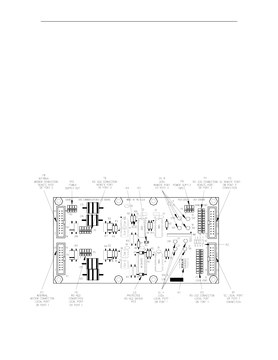
The brown wire from the cable connects to pin 1 of the connector. Pin 1 of the cable must align
with pin 1 of the board connector it is attached to. Use the illustration below to locate the jumpers
and use the chart on the following page to set the jumpers and to connect the terminal block
cables to the proper connectors on the board
Figure 5-4. Site Communications I/O PCB