Your first project, Experiment #130 twin-t oscillator – Elenco 130-in-1 Electronics Playground User Manual
Page 9
-152-
-9-
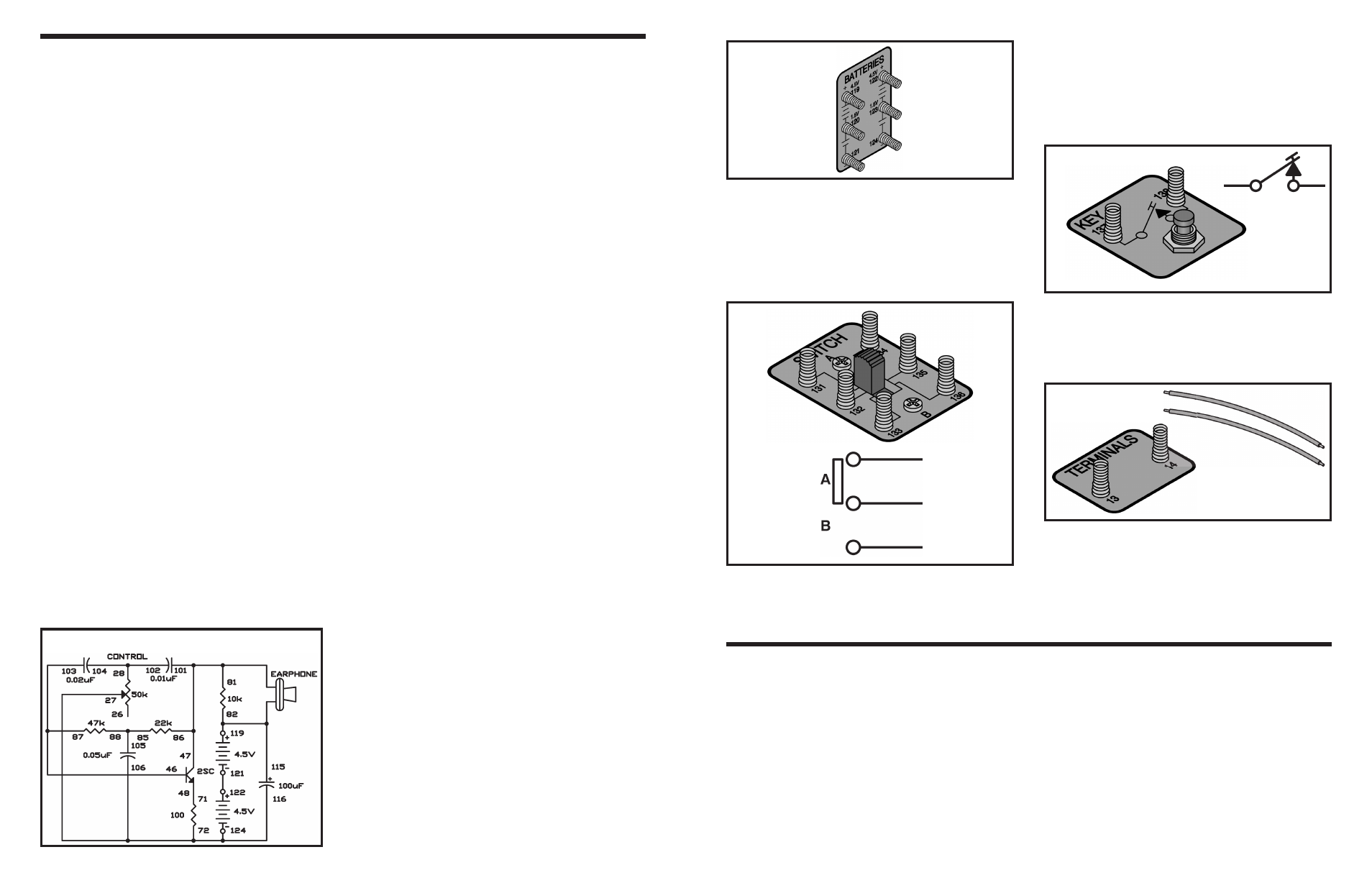
Switch: You know what a switch is – you use
switches every day. When you slide (or flip) to the
proper position, the circuit will be completed, allowing
current to flow through. In the other position a break
is made, causing the circuit to be “off”. The switch that
we will be using is a double-pole, double-throw switch.
You will learn about that later on.
Key: The key is a simple switch—you press it and
electricity is allowed to flow through the circuit. When
you release it, the circuit is not complete because a
break is caused in the circuit’s path. The key will be
used in most circuits often times in signaling circuits
(you can send Morse code this way as well as other
things).
Terminals: Two terminals will be used in some
projects (terminals 13 and 14). They will be used to
make connections to external devices such as an
earphone, antenna or earth ground connection,
special sensor circuits and so forth.
Wires: Wires will be used to make connections to the
terminals.
Your parts and spring terminals are mounted on the
colorful platform. You can see how the wires are
connected to the parts and their terminals if you look
under the platform.
YOUR FIRST PROJECT
A simple wiring sequence is listed for each project.
Connect the wires with appropriate length between
each grouping of terminals listed. When doing the
experiment use the shortest wire that possibly gets
the job done. New groupings will be separated by a
comma, connect the terminals in each group.
As an example, here is the project 1 wiring sequence:
1-29, 2-30, 3-104-106, 4-28-124, 5-41-105, 27-88,
75-87-103-40, 115-42-119, 76-116, 121-22.
Connect a wire between 1 and 29, another wire
between 2 and 30, another between 3 and 104 and
then another wire between 104 and 106. Continue
until all connections are made.
Caution: The last connection in each wiring
sequence is an important power wire; this is
deliberate. It is important that you make this
connection your LAST connection. Damage can occur
if one part of the circuit is completed before another.
Therefore follow the wiring sequence exactly.
The twin-T type audio oscillator is very popular for
use with electronic organs and electronic test
equipment because it is very stable.
The resistors and capacitors in the twin-T network
determine the frequency of oscillation. The letter T is
used because the resistors and capacitors are
arranged in the shape of the letter T in the schematic
diagram. There are two T networks in parallel across
from each other; hence the term twin is used. The
capacitors in series shift the phase of the wave; the
resistors in series supply voltage to the transistor’s
base as well as shifting the phase of the wave.
Carefully adjust the circuit to obtain pure sine wave
output as in the previous two projects. Modify the
control very slowly over its entire range until you hear
a tone in the earphone that is very low and resembles
the lowest note of a large pipe organ. This control
setting should be between 7 and 10 on your dial.
Once the oscillation has started, adjust the control
carefully for the setting that gives the purest sounding
low note near the high end of the dial.
You can experiment with this circuit in many ways. We
suggest you try different values for the 10k
Ω and
470
Ω resistors, and try using higher and lower battery
voltages. Also, if you have a VOM, try measuring
circuit voltages.
Notes:
EXPERIMENT #130 TWIN-T OSCILLATOR
Schematic
Wiring Sequence:
o 72-106-116-27-124
o 28-104-102
o 46-103-87
o 47-101-86-81-EARPHONE
o 48-71
o 119-115-82-EARPHONE
o 85-88-105
o 121-122