Experiment #101: pulse frequency multiplier – Elenco 130-in-1 Electronics Playground User Manual
Page 121
-121-
This is a pulse frequency multiplier with one
transistor. It doubles the frequency of the input signal,
so it is also called a pulse frequency doubler.
The operational amplifier IC acts as a square-wave
oscillator. The output from the oscillator is an AC
signal of about 500Hz.
When you finish the wiring, set the switch to position
A to turn on the power. Connect the earphone to
terminals 93 and 134 and press the key to listen to
the oscillating sound of 500Hz. Note the pitch of the
tone.
Now, connect the earphone to terminals 13 and 14
and press the key. Listen through the earphone; this
time you hear a sound that is an octave higher than
the previous sound. This means the frequency is
doubled to 1,000Hz.
How does this work? The operational amplifier is
configured as an oscillator. Transistor Q1 receives a
signal from the operational amplifier through the
transistor’s base; the base voltage changes with the
oscillations. This result is that opposite phase signals
appear at the transistor’s collector and emitter - when
one signal is at a wave maximum, the other is at the
wave minimum. The two outputs from transistor Q1
are applied to diodes Da and Db. The diodes pass
through only the positive portion of the waves, so
these two signals combine together to produce a
doubled frequency.
Notes:
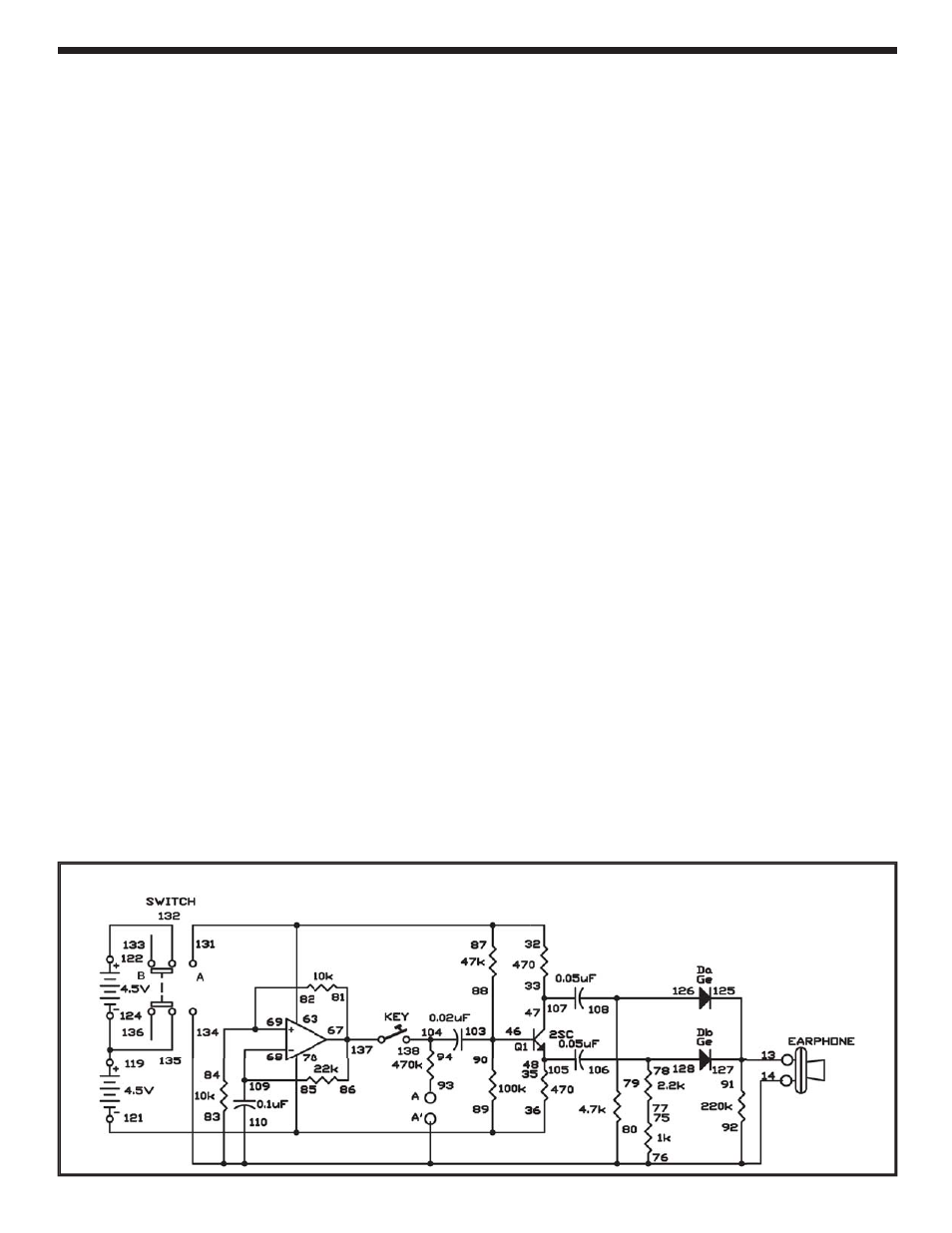
EXPERIMENT #101: PULSE FREQUENCY MULTIPLIER
Wiring Sequence:
125-127-91-13-EARPHONE
134-110-92-80-83-76-14-EARPHONE
32-63-87-131
33-47-107
35-48-105
89-36-70-121
88-90-103-46
81-86-67-137
85-68-109
69-82-84
75-77
78-106-128
79-108-126
94-104-138
119-124-135
122-132
Schematic