Experiment #11: machine gun oscillator, Experiment #117: audio signal hunter – Elenco 130-in-1 Electronics Playground User Manual
Page 22
-139-
-22-
This circuit is what engineers refer to as a “pulse
oscillator”. It will make machine gun like sounds.
There are many different ways to make oscillators. In
this kit, you will build several of them and later on,
you will be told on how they work. In the meantime,
we will just tell you what an oscillator is.
An oscillator is a circuit that goes from high to low
output on its own, or in other words, it turns itself on
and off. A pulse oscillator is controlled from pulses,
like the pulses made from a capacitor charging and
discharging. The oscillator in this kit turns off and on
slowly. However, some oscillators turn off and on
many thousands of times per second. Slower
oscillators can often be seen controlling blinking
lights, such as turn signals in a car or truck. “Fast”
oscillators are used to produce sound. The fastest
oscillators produce radio frequency signals known as
“RF signals”. The RF signal oscillators turn on and
off millions of times per second!
The amount of times an oscillator turns off and on
each second is called the frequency of the oscillator.
Frequency is measured in units called hertz (Hz).
The frequency of this oscillator is about 1 to 12Hz.
The frequency of a radio signal oscillator would be
measured in either MHz (megahertz, meaning a
million hertz) or kHz (kilohertz, meaning a thousand
hertz).
Once you finish wiring, press the key to start the
oscillator. The 50k
Ω resistor is the control; you can
swap it out with other resistors to change the sound
from a few pulses per second to a dozen or so per
second. Also, you can change the frequency of this
oscillator circuit by swapping out other capacitors in
place of the 10
μF. Remember to observe the correct
polarity!
Notes:
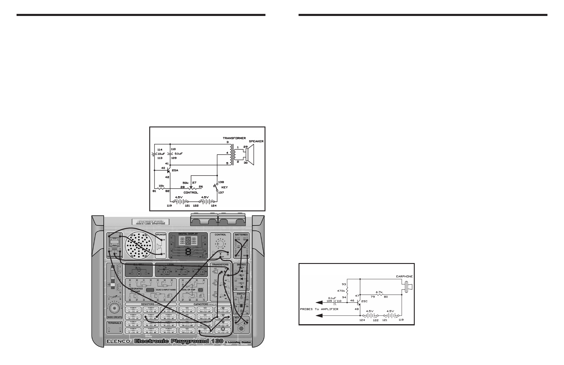
EXPERIMENT #11: MACHINE GUN OSCILLATOR
Wiring Sequence:
o 1-29
o 2-30
o 3-110-114
o 4-27-138
o 5-41-109
o 28-82
o 40-113-81
o 42-119
o 121-122
o 124-137
Schematic
This experiment is a simple transistor audio amplifier
used as an audio signal tracer. You can use this
amplifier to troubleshoot transistor audio equipment.
You can connect the wires to different terminals in the
circuit until you find the stage or component that does
not pass the signal along when a circuit is not working
correctly.
The 0.1
μF input capacitor blocks DC so you can
probe around circuits without worrying about
damaging the circuit.
The amplifier circuit is a common-emitter type. The
transistor’s emitter is connected directly to the input
and the output of the earphone. Its base current is the
self-current type. The current from the transistor
collector provides current to the base (through the
470k
Ω resistor). This provides some stabilizing
negative DC feedback.
You can use this amplifier to check any transistor
radio or amplifier you have that needs fixing.
Notes:
EXPERIMENT #117: AUDIO SIGNAL HUNTER
Schematic
Wiring Sequence:
o 46-110-94
o 47-79-93-EARPHONE
o 124-48-PROBES
o 119-80-EARPHONE
o 109-PROBES
o 121-122