Experiment #51: tone generator using ttl, Experiment #74: non-inverting amplifier – Elenco 130-in-1 Electronics Playground User Manual
Page 68
-68-
We’ve been constructing tones with audio oscillators
for so long that it might seem as if there’s no other
way to produce tones from electronic circuits.
Multivibrators made from NAND gates do the job just
as well.
Connect the earphone to terminals 13 and 14 and
set the switch to A to turn on the power once you
finish wiring this circuit. A tone produced from the
multivibrator will be what you hear. Change the value
of the capacitors from 0.1
μF to 0.5μF. What effect
does this have on the sound?
Try using different capacitors within this experiment.
Don’t try using any of the electrolytic capacitors,
(terminals 111-118). To vary the tone, try to arrange
the circuit so you can switch different value
capacitors in and out of this circuit.
Notes:
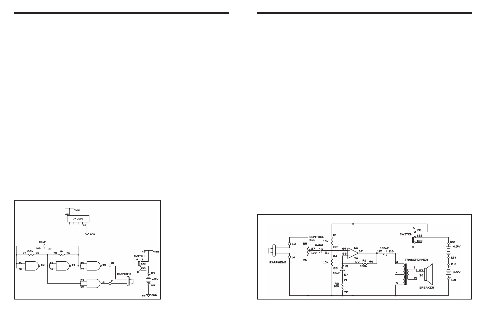
EXPERIMENT #51: TONE GENERATOR USING TTL
Wiring Sequence:
o 49-131
o 50-51-77-109
o 52-53-54-60-59-75-78
o 55-57-56-76-110
o 62-121
o 119-132
o 58-13-EARPHONE
o 61-14-EARPHONE
Schematic
-93-
In Projects 72 and 73 (“Non-inverting Dual Supply
Op Amp,” and “Inverting Dual Supply Op Amp,”
respectively), we used the operational amplifier with
two power sources. In this experiment, we will make
a single-power source, non-inverting microphone
amplifier. Again, the earphone works as a
microphone.
Slide the switch to position B and assemble the
circuit. When you competed the wiring, slide the
switch to position A to turn on the power, alternate
the control clockwise, and speak into the
microphone. The experiment works just like Projects
72 and 73, but you’ll notice something different.
The contrast comes from the gain of this microphone
amplifier. It is still determined by R1 and R2, but now
it’s much bigger. Can you observe why? Yes, we use
the 100
Ω resistor in place of the 1kΩ resistor from
the last two experiments. Try changing R2 to 1k
Ω,
and the gain drops to the level of the last
experiments.
In this experiment, two power sources are connected
in series to operate the dual operational amplifier at
9V. But the operational amplifier can work at half this
voltage, at 4.5V. See what occurs when you
disconnect the operational amplifier from battery
terminal 122 and connect it to terminal 119.
Notes:
EXPERIMENT #74: NON-INVERTING AMPLIFIER
Wiring Sequence:
o 1-29
o 2-30
o 3-116
o 27-112
o 71-114
o 81-63-131
o 67-90-115
o 89-68-113
o 84-82-69-111
o 119-124
o 122-132
o 121-26-70-83-72-5-14-EARPHONE
o 28-13-EARPHONE
Schematic