Experiment #31: “nand” dtl circuit with display, Experiment #96: vco – Elenco 130-in-1 Electronics Playground User Manual
Page 46
-46-
You will not be able to find the word NAND in your
dictionary (unless it is a computer or electronic
dictionary). This term means inverted or Non-AND
function. It creates output conditions that are the
opposite of the AND circuits output conditions. When
both inputs A and B are high the NAND output is low.
If either or both of the inputs are low then the output
is high. The symbol for logic looks like the AND
symbol but with a small circle at the output. AB is the
representation of the function.
The NPN transistor stays off when either or both
terminals A and B are connected to terminal 124
(logic low terminal), and negative current flows
through the diode(s). The LED remains off. Both
diodes allow positive voltage to flow through them
when both of the inputs are connected to terminal
119 (logic high terminal). The NPN transistor is
turned on by positive voltage, thus the current flows
to light the L on the LED.
Notes:
EXPERIMENT #31: “NAND” DTL CIRCUIT WITH DISPLAY
Wiring Sequence:
o 81-20-19-18-119
o 25-47
o 82-46-128-126
o 48-130
o 121-122
o 124-129
o 125-(to 124 “LOW” or 119 “HIGH”)
o 127-(to 124 “LOW” or 119 “HIGH”)
Schematic
-115-
VCO? What’s that? VCO stands for voltage
controlled oscillator, and as the name implies, this
oscillator changes its oscillation frequency according
to the voltage applied to the circuit. The circuit
creates two different output signals that have
triangular and square waves.
When you finish the wiring sequence, slide the switch
to position A to turn on the power. Turn the control
slowly while you listen to the sound from the
earphone. The sound becomes lower when you turn
the control clockwise.
Turning the control changes the voltage at terminal
27, which changes the 0.01
μF capacitor’s charging
and discharging times, which changes the oscillator
frequency. The output signal from the first operational
amplifier is a triangular wave signal is at terminal 67,
and is applied to terminal 65 of the second amplifier.
The second amplifier acts as a comparator, and
produces a square wave signal at terminal 64.
Notes:
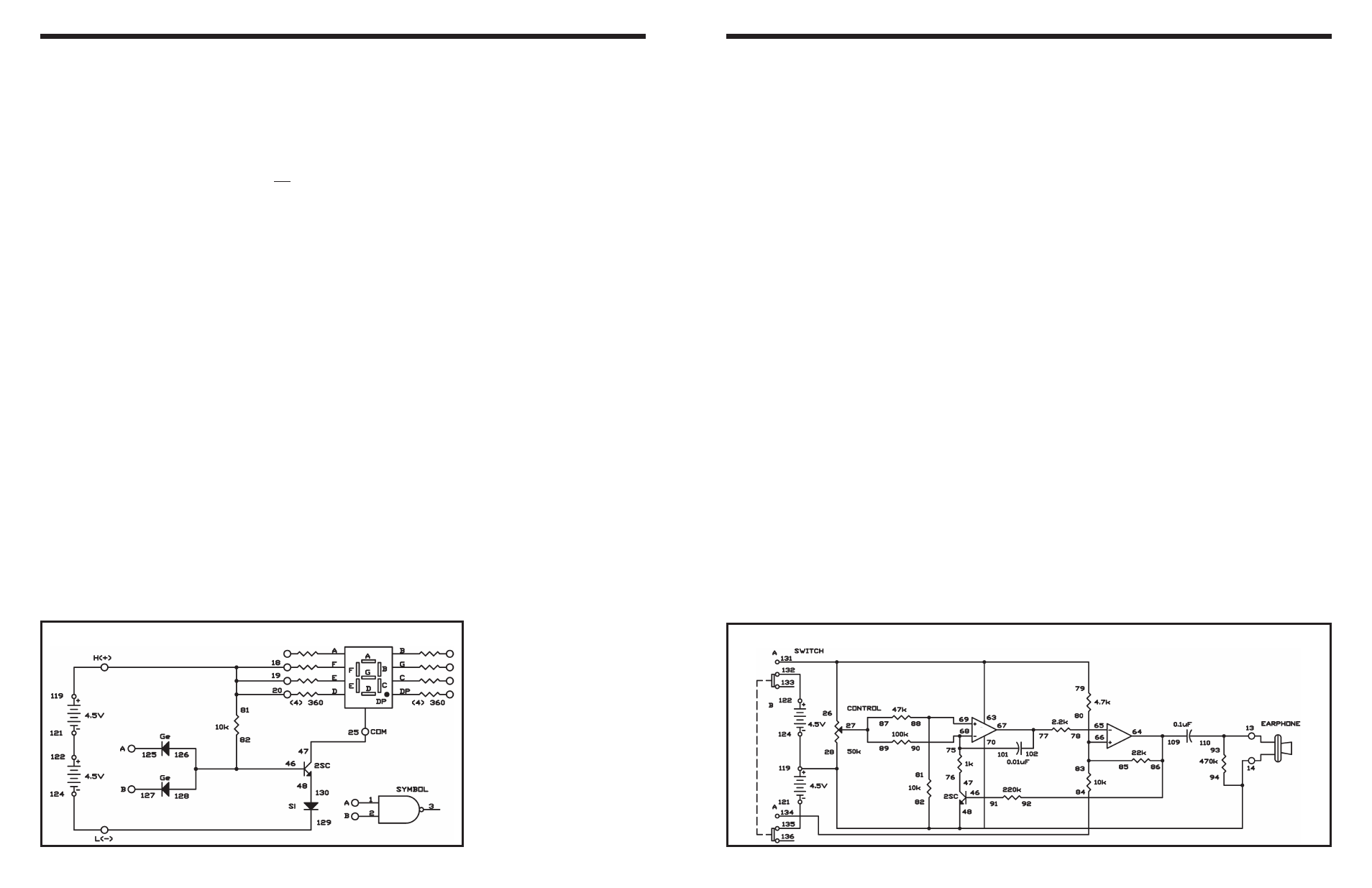
EXPERIMENT #96: VCO
Wiring Sequence:
o 79-63-26-131
o 27-87-89
o 46-91
o 47-76
o 86-92-109-64
o 65-78
o 66-80-83-85
o 67-102-77
o 68-90-101-75
o 69-88-81
o 84-70-134
o 121-135
o 122-132
o 124-119-28-48-94-82-14-EARPHONE
o 110-93-13-EARPHONE
Schematic