Experiment #50: astable multivibrator using ttl, Experiment #75: dual-supply differential amplifier – Elenco 130-in-1 Electronics Playground User Manual
Page 67
-67-
Multivibrator circuits can be created from NAND
gates. This experiment is an example of an astable
multivibrator – are you able guess what astable
means? Generate a guess, and complete this project
to see if you were right.
To turn the circuit on, connect terminals 13 and 14.
LED 1 begins to flash. Astable means the
multivibrator’s output keeps switching back and forth
between 0 and 1. So far most of the multivibrators
that you have built do the same things.
You shouldn’t trouble figuring out how this particular
circuit works. The 100
μF capacitor is the key. In
place of the 100
μF capacitor, try using other
electrolytic capacitors and see what result they have
on LED 1 (Be sure to apply the correct polarity.)
By now can see why NAND gate ICs are so useful.
Quad two-input NAND ICs, like the one in this set,
are among the most widely used electronic
components in the world, because there are so many
different types of circuits that they can be used in.
Notes:
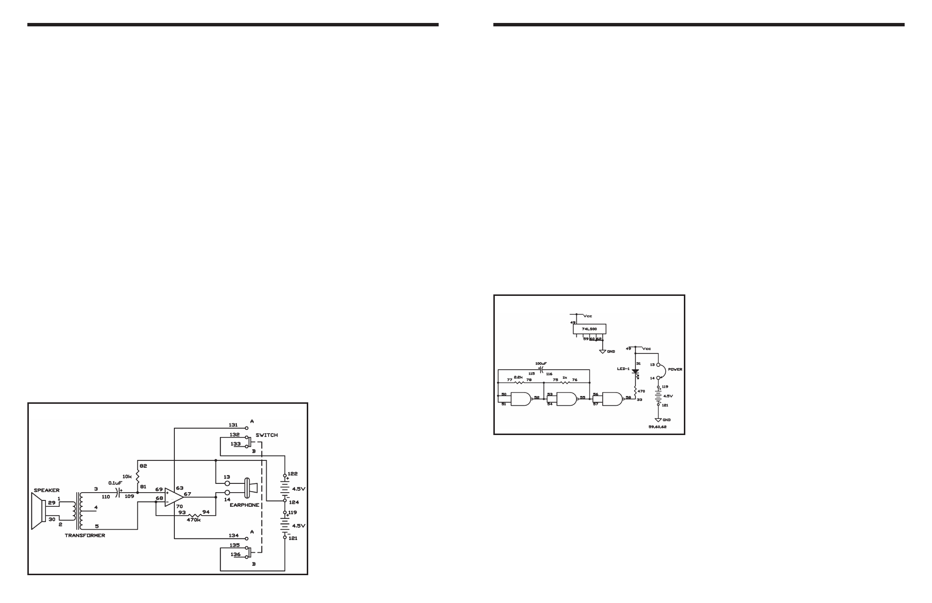
EXPERIMENT #50: ASTABLE MULTIVIBRATOR USING TTL
Schematic
Wiring Sequence:
o 13-49-31
o 14-119
o 33-58
o 50-51-77-115
o 54-53-52-75-78
o 55-56-57-76-116
o 59-60-62-121
o 13-14 (POWER)
-94-
This is the last in the series of microphone amplifiers.
Now you will use the operational amplifier as a
differential amplifier. It is a two-power source type
amplifier, and this time we use the speaker as a
microphone.
Slide the switch to position B and construct the
circuit. When you finish the wiring, apply the
earphone to your ear, slide the switch to position A
to turn on the power, and tap the speaker lightly with
your finger.
In this circuit the operational amplifier is configured
to amplify the difference between its positive (+) and
negative (–) inputs, so we call it a differential
amplifier. The speaker is connected to the
transformer, which is then connected to the
amplifier’s inputs, so the speaker signal will be
amplified.
In a speaker, an electrical signal flows through a coil
and creates a magnetic field; the magnetic field
changes as the electrical signal changes. The
magnetic field is used to move a small magnet, and
this movement creates variations in air pressure,
which travel to your ears and are interpreted as
sound.
This circuit uses the speaker as a microphone. In this
arrangement, your voice creates variations in air
pressure, which move the magnet inside the
speaker. The moving magnet’s magnetic field creates
an electrical signal across both ends of a coil. This
small signal is applied to the primary of the
transformer, which then results in larger signal at the
secondary side of the transformer.
This circuit is simplified by using the speaker as a
microphone. To use the earphone as in previous
experiments, you would have to make a far more
complex circuit.
Notes:
EXPERIMENT #75: DUAL-SUPPLY DIFFERENTIAL AMPLIFIER
Wiring Sequence:
o 1-29
o 2-30
o 3-110
o 5-68-93
o 63-131
o 69-81-109
o 70-134
o 121-135
o 122-132
o 124-119-82-13-EARPHONE
o 94-67-14-EARPHONE
Schematic