Experiment #102: white noise maker – Elenco 130-in-1 Electronics Playground User Manual
Page 39
-122-
-39-
In this project you will see how to turn on an LED by
using a transistor and a CdS cell.
Think of the CdS cell as a resistor that changes its
resistance based upon the amount of light that falls
upon it. In the dark the resistance is very high,
around 5 megohms (M
Ω, 5 million ohms); in bright
sunlight, it can decrease to about 100
Ω or less.
To test this easily; just set your VOM to the resistance
function and then connect it to the CdS cell. Now hold
you hand over the CdS cell and note its resistance.
Read the resistance again once you have moved
your hand.
For a switch you can use the NPN transistor. This
transistor turns on when sufficient positive voltage is
applied to its base. Positive voltage leads from the
positive terminal of the battery, then to the CdS cell,
to the control, and then finally to the 10k
Ω resistor.
The amount of voltage applied to the transistor’s
base is determined by the total resistance value of
the CdS, the control, and the 10k
Ω resistor. The
amount of light striking the cell and the control setting
change the base voltage - making it either high or
low enough to turn on the transistor. Using your
voltmeter on the control, try to change the control
position while casting a shadow over the CdS to
verify the voltage change. When light changes over
the CdS, adjust the control so that the transistor turns
on and off.
Under bright light the circuit displays a 1. You can
connect the wires to display any number you desire.
1 might be considered to be a binary digit, showing
logic “high” (H or ON), as indication of the presence
of a bright light on the CdS cell. Can you rewire this
circuit to display another character to indicate this
condition?
Notes:
EXPERIMENT #25: LED DISPLAY WITH CdS AND TRANSISTOR
Wiring Sequence:
o 15-21-23-119
o 16-28
o 25-47
o 124-26-48
o 27-82
o 46-81
o 121-122
Schematic
White noise is a noise that has a wide frequency
range. One kind of white noise is the static noise you
hear when you tune your FM radio to an area with
no station. When you play electronic musical
instruments, you can use white noise, a normally
useless noise, as a sound source.
When you complete building this circuit, set the
switch to position A to turn on the power. Look at the
schematic. You will use the noise that is generated
when you apply a reverse voltage to the base and
the emitter of transistor Q1.
IC 1 acts as an oscillator. The output of this oscillator
is rectified by diodes D1 and D2, and flows to Q1. IC
2 amplifies the noise so that you can hear it through
the earphone.
Notes:
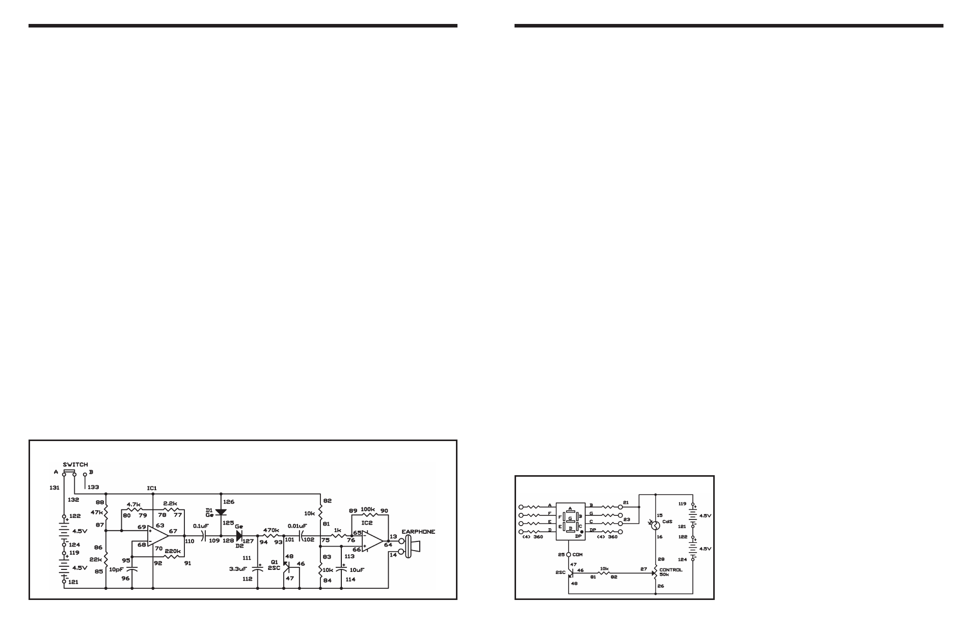
EXPERIMENT #102: WHITE NOISE MAKER
Wiring Sequence:
o 64-90-13-EARPHONE
o 121-114-112-46-47-70-96-84-85-14-EARPHONE
o 93-48-101
o 94-111-127
o 82-88-63-132-126
o 76-89-65
o 113-66-81-83
o 77-91-67-110
o 68-95-92
o 69-80-87-86
o 78-79
o 109-128-125
o 119-124
o 122-131
o 102-75
Schematic