Experiment #34: “buffer” gate using ttl, Experiment #92: burglar buzzer – Elenco 130-in-1 Electronics Playground User Manual
Page 50
-50-
Have you ever wondered what happens once you
start adding digital circuits together, using the output
of one as the input of another? You’ll find out when
you build this project.
A quad two-input NAND gate IC, is one of the
integrated circuits contained in your kit. Some of
these words will probably be a confusing at first. IC
is short for integrated circuit. Something that contains
many transistors, diodes, and resistors in one small
package is an integrated circuit. This NAND gate
uses TTL, short for Transistor-Transistor-Logic,
because it is mostly constructed using transistors.
Quad means four. There are four separate NAND
gate circuits, in this IC each receiving two inputs. Two
input terminals are for Each NAND gate.
As you build this project make sure to consult to the
schematic. This circuit takes the output from one
NAND gate, and uses it for both inputs to the second
(both inputs for the two NANDs are always the same
here). What do you think happens if the input to the
first NAND is 1, after learning about NANDs? If the
first input is 0? Attempt to figure it out before building
this project.
Set the switch to B before completing the wiring. To
turn the power on, connect terminals 13 and 14.
What happens to LED 1? Set the switch to A. LED 1
lights up.
1 is the input when the switch is set to A, and 0 is the
input when the switch is at B. When the input to the
first NAND is 1, its output is 0. But the 0 output of the
first NAND is the input to the second. The 0 input to
the second makes its output become 1, lighting the
LED.
Notes:
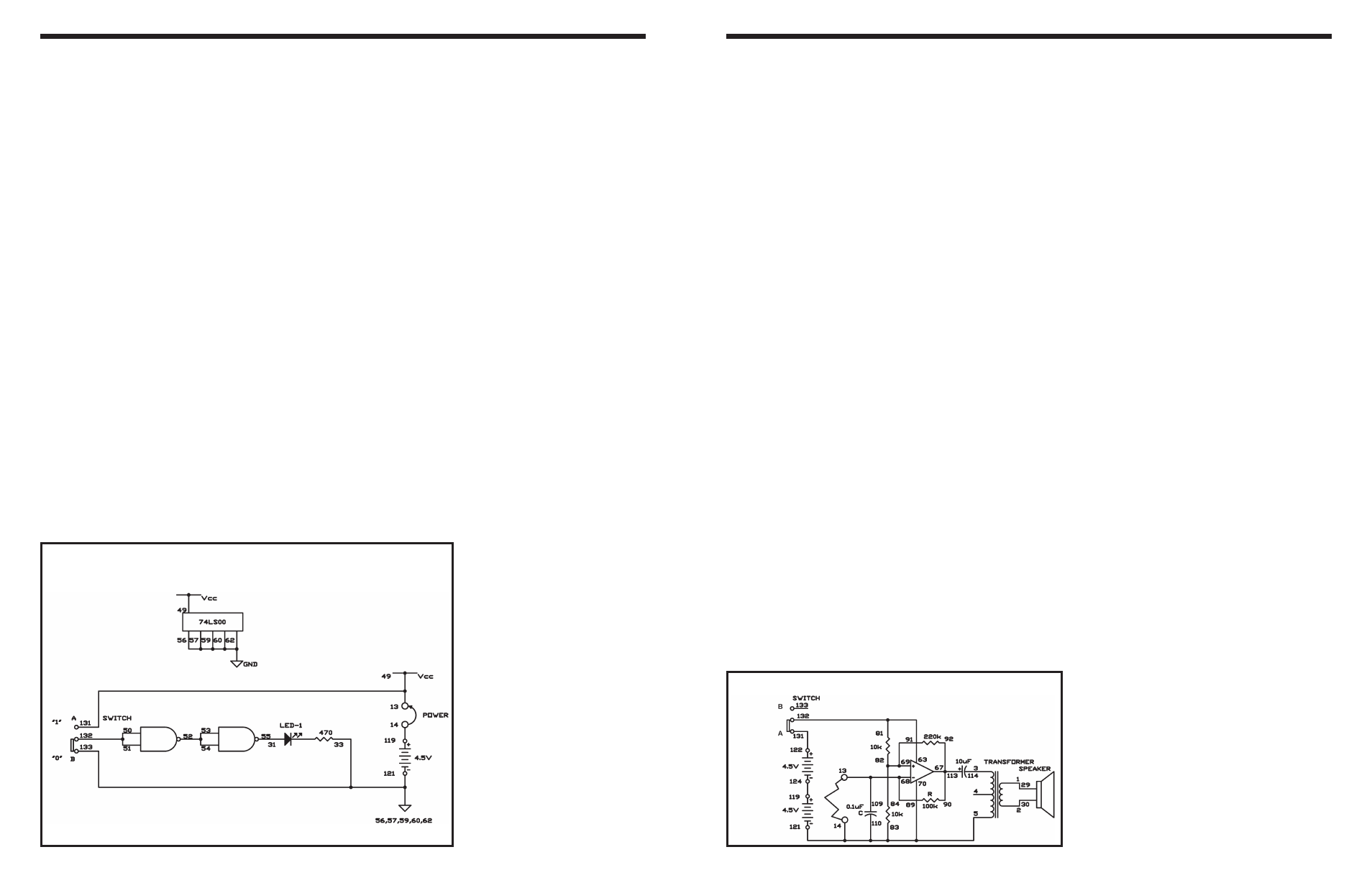
EXPERIMENT #34: “BUFFER” GATE USING TTL
Wiring Sequence:
o 13-49-131
o 14-119
o 31-55
o 33-56-57-59-60-62-133-121
o 50-51-132
o 52-53-54
o 13-14 (POWER)
Schematic
-111-
This burglar alarm makes a buzzing sound when
anyone sneaking into your house trips over a wire
and breaks it off or disconnects it from a terminal. Try
to figure out how to connect a switch to the door of
your house, so that the alarm sounds when a burglar
opens the door, instead of stretching out the wire.
Start by sliding the switch to position B and
assembling the circuit. When you complete the
wiring, connect the terminals 13 and 14 to the long
wire, and slide the switch to position A to turn on the
power. No sound comes from the speaker, at this
time.
Detach the wire from terminal 13,to test the alarm.
The speaker gives out a beep. This beep is the alarm
that tells you a burglar is about the break into your
house.
As you can observe in the schematic, this burglar
alarm uses the operational amplifier as an astable
multivibrator, as the electronic buzzer in the last
experiment did. You can change its frequency by
using different values for the 10k
Ω resistor and the
0.1
μF capacitor. Note how the tone of the buzzer
alters when you set the 10k
Ω resistor to 47kΩ or
switch the 100k
Ω and 220kΩ resistors with each
other.
Notes:
EXPERIMENT #92: BURGLAR BUZZER
Schematic
Wiring Sequence:
o 1-29
o 2-30
o 3-114
o 5-14-83-70-110-121
o 13-89-68109
o 81-63-132
o 67-90-92-113
o 69-82-84-91
o 119-124
o 122-131
o 13-14 (LONG WIRE)