Experiment #44: “exclusive or” gate using ttl, Experiment #82: introducing the schmitt trigger – Elenco 130-in-1 Electronics Playground User Manual
Page 60
-60-
Since we have made up some digital circuits by
combining NAND gates, it makes sense that we
make XOR gates too. This circuit will show you how.
Before you complete this circuit set the switch to B.
Connect the terminals 13 and 14, once you have
finished the wiring. Does anything happen to LED 1
when you press the key? Release the key now and
set the switch to A. What occurs with the LED 1?
Now press the key while leaving the switch at A.
What happens with the LED 1 now?
As long as the inputs are different, output is 1. The
output of the XOR gate is 0, as long as both of the
inputs are the same - either 0 or 1.
Its thinking cap time again. Follow each 0 or 1 input
throughout the circuit until they reach the output. It
will help if you mark 0 or 1 on the input and the output
of each NAND gate on the schematic.
Notes:
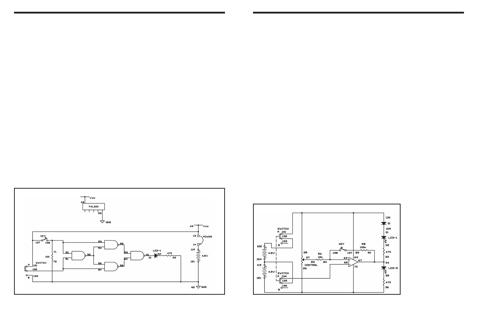
EXPERIMENT #44: “EXCLUSIVE OR” GATE USING TTL
Wiring Sequence:
o 13-49-131-137
o 14-119
o 31-61
o 72-62-33-133-121
o 71-50-53-138
o 57-51-132
o 54-52-56
o 55-59
o 58-60
o 13-14 (POWER)
Schematic
-101-
Now you are going to use the operational amplifier
as a comparator and as a Schmitt trigger circuit. As
long as its input voltage exceeds a certain value, the
operational amplifier will produce a signal. View the
schematic: can you see how it works? The input
level that turns on the output is higher than the level
than turns it off. So once a Schmitt trigger circuit
turns on, it stays on unless the input drops
significantly. We call this type of operation a
“hysteresis loop.”
Build the circuit, but don’t press the key yet. The
operational amplifier serves as a comparator in this
state. When you alternate the control, LEDs 1 and 2
take turns lighting at some point. Note that this point
doesn’t alter whether you turn the control clockwise
or counterclockwise.
Now push the key and you have a Schmitt trigger
circuit, which makes a hysteresis loop. Turn the
control and see how the circuit operation is different
from before.
As the ratio of resistors RB/RA increases, the width
of hysteresis becomes narrower. Try using different
values for RA and RB, and notice how the width
changes.
Notes:
EXPERIMENT #82: INTRODUCING THE SCHMITT TRIGGER
Wiring Sequence:
o 70-36-26-121
o 27-83
o 63-28-130-131
o 34-33-67-90
o 68-134
o 84-69-138
o 89-137
o 119-124-135
o 122-132
o 31-129
Schematic