Experiment #17: capacitor discharge flash, Experiment #110: am code transmitter – Elenco 130-in-1 Electronics Playground User Manual
Page 30
-131-
-30-
In this circuit single pulses of high voltage electric
energy are generated by suddenly discharging a
charged capacitor through a transformer. Automobile
ignition systems use a similar capacitor-discharge
reaction.
The operation of this circuit is simple but the
concepts involved are important to helping you
understand more complicated circuits. If you have
access to an oscilloscope, you can scientifically
measure the energy that is discharged through the
transformer.
The 470
μF capacitor stores up energy as the
batteries supply millions of electrons to the
capacitors negative electrode. Meanwhile the
batteries draw the same number of electrons from
the capacitors positive electrode so that the positive
electrode is lacking electrons. The current must pass
through the 4.7k
Ω resistor, so it requires at least 12
seconds for the capacitor to receive the full 9V
charge from the batteries.
The amount of charge a capacitor can store depends
on its capacitance value and the voltage applied
across it. This represents the amount of electrons
displaced in the electrode.
The amount of electrons in a capacitor’s electrode is
measured in coulombs. The quantity of one coulomb
is 6,280,000,000,000,000,000 electrons (6.25 x
10
18
).
The charge in either electrode of the capacitor is
determined by multiplying the capacitance (C) by the
voltage across the capacitor (E). (Q = C x E). The
470µF (470 x 10
-6
F) capacitor at 9V is calculated as
follows:
Q = C x E = 470 x 10
-6
x 9 = 4.23 x 10
-3
coulombs
or:
470 x 0.000001 x 9 = 4.23 x 10
-3
coulombs
(265,564,400,000,000 electrons)
Pressing the key causes the above number of
electrons to pass through the transformer winding in
a very short time and induces a high voltage in the
secondary winding. Thus causing the LED to flash.
An oscilloscope is an electronics measurement
instrument used by engineers and technicians. If you
have access to one, connect it (with help from
someone who knows how to use it) to terminal 3 and
terminal 5 of the transformer to indicate the presence
of 90V or more. The indicated voltage is produced
when the charge held by the capacitor is released
into the transformer.
Notes:
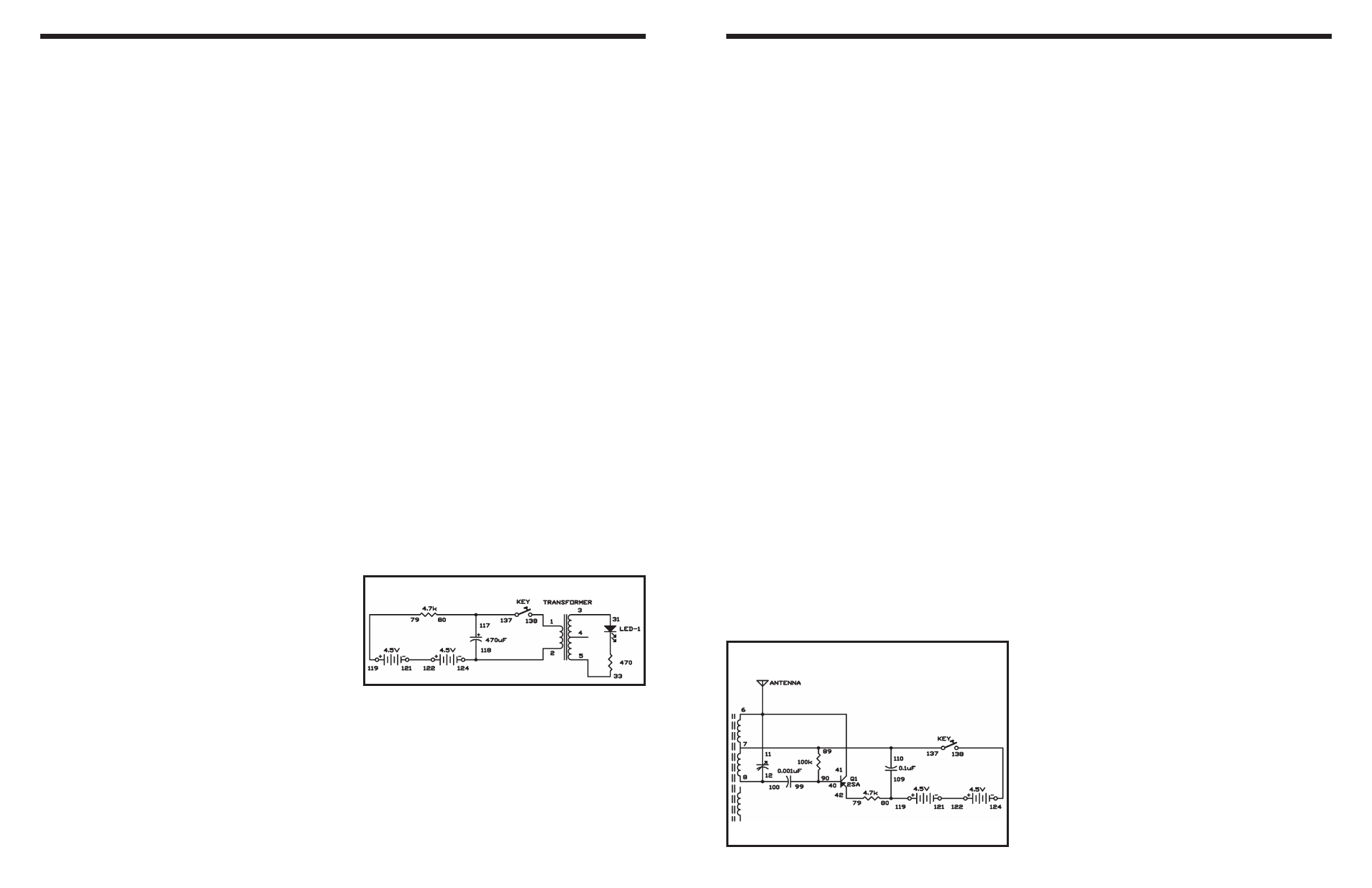
EXPERIMENT #17: CAPACITOR DISCHARGE FLASH
Wiring Sequence:
o 1-138
o 2-118-124
o 3-31
o 5-33
o 79-119
o 80-117-137
o 121-122
Schematic
This circuit is a simplified but effective code transmitter
similar the kind used by military and amateur radio
operators around the world. As the key is pressed and
released, the transmitter turns on and off in sequence.
The code send out by the transmitter can be received
using an AM radio. The radio should be tuned to a
weak station. When the transmitter signal mixes with
the station’s signal it produce an audio tone, called a
beat note. The code signal transmitted is the beat note
you hear on the radio. Use the tuning capacitor to
tune this transmitter until you can hear the beat note
in the radio when you press the key.
If your communications receiver has a beat frequency
oscillator (BFO), you can receive the carrier wave
(CW) signal of this transmitter on a communications
receiver, without tuning to another station,. The BFO
beats with your transmitter’s CW signal and produces
the tone.
The frequency of this oscillator sends out an RF signal
because is very high (500,000Hz to 1,600,000Hz).
Tuning to a weak AM station first, then sending a
signal slightly off from the station frequency, you can
hear the beat note that you produced.
This type of transmission and reception of CW signals
is very efficient and most reliable type of transmission
for some emergencies. You might find that you do not
need an antenna or only 1- 3 feet (about 60-90 cm) of
wire.
Notes:
EXPERIMENT #110: AM CODE TRANSMITTER
Schematic
Wiring Sequence:
o 41-6-11-ANT
o 7-89-110-137
o 8-12-100
o 40-90-99
o 42-79
o 80-109-119
o 121-122
o 124-138