Experiment #55: transistor timer using ttl, Experiment #70: operational amplifier comparator – Elenco 130-in-1 Electronics Playground User Manual
Page 72
-72-
This is another type of one-shot circuit; in this project
you hear the effects of the multivibrator. From the
schematic you can see that this experiment uses a
combination of simple components and digital
electronics. Once you press the key, the 100
μF
capacitor is charged and lets the NPN translator in
the left corner of the schematic operate. You can
observe that the collector of this transistor serves as
both inputs for the first NAND gate.
The digital portion in the middle controls the PNP
transistor on the right side of the schematic. To turn
the power on, set the switch to A. You hear a sound
from the speaker when the output of the first NAND
is 1, and the multivibrator is enabled.
This sound will continue until the 100
μF capacitor
discharges, preventing the first transistor from
operating. When the output of the first NAND
becomes 0, the multivibrator shuts off. With the
component values as shown in the schematic, the
sound will last for about 10 seconds. Try substituting
the 22k
Ω with the 47kΩ or the 100kΩ resistor and see
what occurs.
Part B: press the key and release it. When the sound
stops, remove the wire between springs 52 and 54.
What happens? Can you explain why?
Notes:
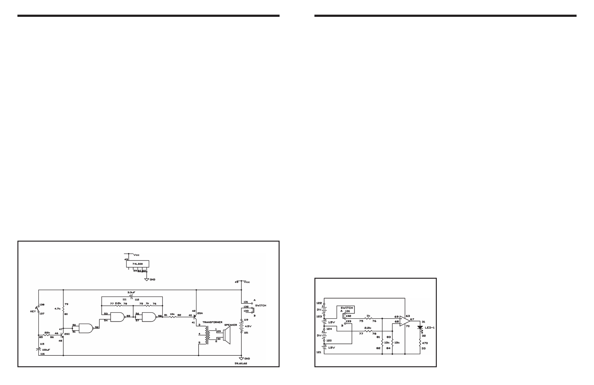
EXPERIMENT #55: TRANSISTOR TIMER USING TTL
Wiring Sequence:
o 1-29
o 2-30
o 3-41
o 5-59-60-62-48-116-121
o 40-82
o 79-49-42-131-138
o 46-86
o 47-50-51-80
o 52-54
o 53-77-111
o 55-57-56-75-78
o 58-76-81-112
o 85-115-137
o 119-132
Schematic
For this section you will need some basic
understanding about the operational amplifier
integrated circuit. First, we can use separate power
sources or we can use one power source for both the
circuit and the IC.
The operational amplifier (often called “op amp” for
short) can be operated as a non-inverting amplifier,
an inverting amplifier, or a differential amplifier. A
non-inverting amplifier reproduces an input signal as
an output signal without any alteration in polarity. An
inverting amplifier does the reverse: its output has
the reverse polarity of its input. The differential
amplifier has an output that is the contrast between
the strengths of the two input signals.
Comparing two voltages and telling you which one is
stronger than the other is the job of a comparator. We
call the controlled voltage the reference voltage
because we use it as a reference for measuring other
voltages. The voltage that is compared is the input
voltage.
The reference voltage in this experiment is about
3.7V. It is connected to terminal 68 of one of the op
amp integrated circuit. Input voltage is connected to
terminal 69 of the same IC. The LED will light if this
input voltage is higher than the reference voltage,
and the LED stays off if it is lower. The operational
amplifier acts as an inverting amplifier for the
reference voltage to keep the LED turned off, or as a
non-inverting amplifier to light the LED.
Build the experiment and then set the switch to
position A. This supplies an input of 6V. The LED lights
because the input voltage is higher than the reference
voltage. Now slide the switch to position B. This
supplies an input voltage of 1.5V. The comparator IC
does not turn on the LED, because the input voltage
is now lower than the reference voltage.
Notes:
EXPERIMENT #70: OPERATIONAL AMPLIFIER COMPARATOR
Schematic
-89-
Wiring Sequence:
o 31-67
o 84-82-33-70-121
o 63-122
o 68-83-78
o 69-81-76
o 75-132
o 77-119-124
o 120-133
o 123-131