Experiment #9: strobe light, Experiment #119: square wave oscillator – Elenco 130-in-1 Electronics Playground User Manual
Page 20
-141-
-20-
In this experiment you will be creating an oscillator
circuit that doesn’t make sound using a speaker or
an earphone. Instead the circuit will produce light
with an LED. This will give you an idea of how larger
strobe lights work. When you press the key, watch
LED 1. At certain intervals the light turns on and off.
With the 50k
Ω control you can control the rate of
blinking.
Try substituting a capacitor with a lower value for the
100
μF capacitor to see how an oscillator works.
Make a prediction about what you think will happen?
Were you correct?
Notes:
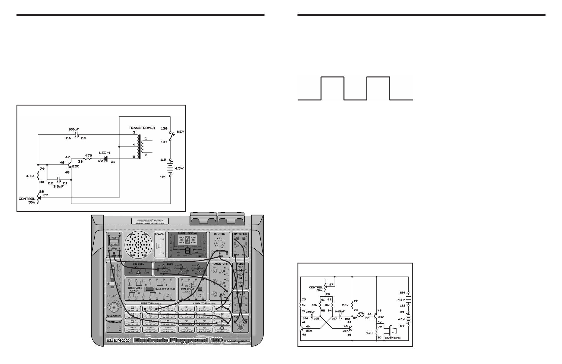
EXPERIMENT #9: STROBE LIGHT
Wiring Sequence:
o 3-115
o 4-27-138
o 5-31
o 28-80
o 33-47
o 79-116-112-46
o 111-48-121
o 119-137
Schematic
Multivibrator oscillators produce square waves, and
you can use square waves as test signals. You should
be familiar with multivibrator circuits from previous
experiments. The name square wave comes from the
pattern produced by the signal on an oscilloscope
(shown below).
Build this circuit and you will hear the sound produced
by a square wave signal. You can differ the pitch and
the frequency of the signal by modifying the control.
This varies the current supplied to the PNP transistor
bases.
Notes:
EXPERIMENT #119: SQUARE WAVE OSCILLATOR
Schematic
Wiring Sequence:
o 77-75-48-27-124
o 28-81-83
o 40-107-84
o 41-106-76
o 119-42-45-80-EARPHONE
o 43-105-82
o 78-87-108-44
o 46-88
o 47-79-EARPHONE
o 121-122