Experiment #21: series and parallel resistors, Experiment #107: timer – Elenco 130-in-1 Electronics Playground User Manual
Page 34
-127-
-34-
In this project, you will discover what happens when
you connect resistors in series and in parallel. You
will see the LED-1 on the panel flash on and off when
you finish wiring.
See what happens to the LED on side A and then on
side B when you slide the switch. There is no change
at all. The schematic shows that two 10k
Ω resistors
are connected in series to side A of the switch, and
one 22k
Ω resistor is connected to side B. The
resistors connected in series on side A are equal to
the sum of each resistor’s value – so 20k
Ω is the total
resistance of the resistors. This is about the same as
22k
Ω resistance in side B. So the LED shows no
change when you move the switch.
The LED becomes brighter when you press the key.
By looking at the schematic, you will see that resistor
R1 (470k
Ω) is connected to the LED in series. The
resistor controls the flow of current to the LED. The
total resistance decreases when you press the key,
R1 and resistor R2 (100
Ω) are connected in parallel.
The LED becomes brighter because of the amount of
current flowing to it increases, when the amount of
resistance decreases.
Calculating the total resistance for resistors connected
in parallel is not as easy as when resistors are
connected in series. You must multiply the values
together, and then divide the product by the sum of
values. In this case, the total resistance is:
Connect now terminals 13-14. As shown in the
schematic, this connects the 22k
Ω resistor in parallel
with the two 10k
Ω resistors. Is there any change in
the LED? The flashes on and off of the LED are at
shorter intervals because the resistance connected
to the slide switch decreases. Try to calculate the new
resistance value. The new value is about 10.5k
Ω.
This circuit is known as a multivibrator. A multivibrator
is an oscillator that uses components that direct
current back to each other. From the schematic you
can see that the 10
μF and the 100μF capacitors
discharge through the transistors. This multivaibrator
circuit controls the oscillations to create the flash
through the LED at certain intervals.
You can now see that resistors and capacitors have
opposite effects when they are connected in series
or parallel. Be careful - it is easy to get confused
about which one increases or decreases in strength.
Notes:
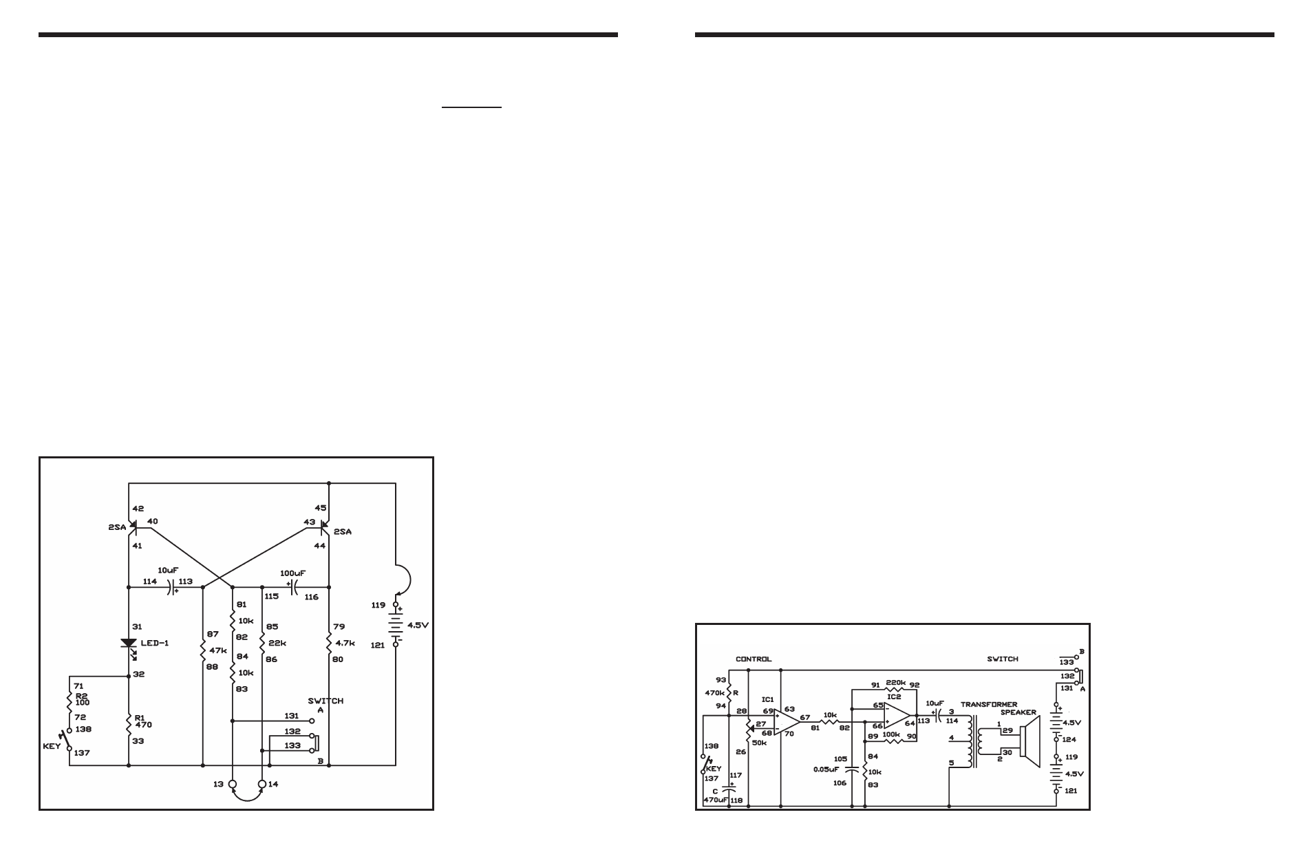
EXPERIMENT #21: SERIES AND PARALLEL RESISTORS
Wiring Sequence:
o 31-41-114
o 79-116-44
o 40-115-85-81
o 43-113-87
o 32-71
o 72-138
o 82-84
o 13-83-131
o 14-86-133
o 33-80-88-137-132-121
o 45-42-119
Schematic
470 x 100
(470 + 100)
= 82
Ω
Here’s a timer you can use for taking timed tests or
simply for knowing when an amount of time has
passed. You can preset this timer for up to
approximately 15 minutes. When the time is up, it
gives out a continuous buzzer sound until you turn
off the power or press the key to reset the circuit.
After you build this experiment, set the control to
position 2 on the dial and slide the switch to position
A to turn on the power. Hold a stopwatch and start it
when you press the key. The timer makes a buzzing
sound in about 30 or more seconds.
Set the control to each division on the dial from 2 to
8, and note how long it takes the timer to produce a
sound. Setting the timer’s calibration - the time that
passes at each setting of the dial - requires a lot of
patience, but it is necessary for making sure your
timer works accurately. After you set the calibration,
you need to make a graph showing each control
position and the time it takes for the buzzer to sound.
Then your tester is ready for use.
Scan the schematic. The control changes the
reference voltage of the comparator (IC 1). The
resistor R and the capacitor C determine the timer
setting. When the voltage applied to the positive (+)
terminal of IC 1 exceeds the reference voltage, the
alarm sounds.
The operational amplifier has high input impedance
(input resistance), so its current loss is very small,
and you can use it to make a timer with a very long
setting. IC 2 works as an astable mulitivibrator that
produces the buzzer sound.
Notes:
EXPERIMENT #107: TIMER
Wiring Sequence:
o 1-29
o 2-30
o 3-114
o 5-83-70-106-118-137-26-121
o 93-63-28-132
o 92-90-64-113
o 65-105-91
o 66-82-84-89
o 67-81
o 94-69-117-138
o 119-124
o 122-131
Schematic