Experiment #16: flip flopping, Experiment #111: am radio station – Elenco 130-in-1 Electronics Playground User Manual
Page 29
-132-
-29-
How about we take a break? This circuit is for
entertainment. The numbers 1 and 2 will flash on the
display in the circuit. This might remind you of some
neon signs that have eye-catching advertisements
on them.
A “flip-flop” circuit controls the LED display in this
experiment. In later projects you will be learning more
about flip-flop circuits. Try a different value for the
capacitors to see the effects on the operation speed.
Try and rewire the LED display to flash numbers
other than 1 and 2. Try placing higher values in place
of the 22k
Ω and 4.7kΩ resistors. Do not use lower
values for any of the resistors or else you could
damage the transistors.
Notes:
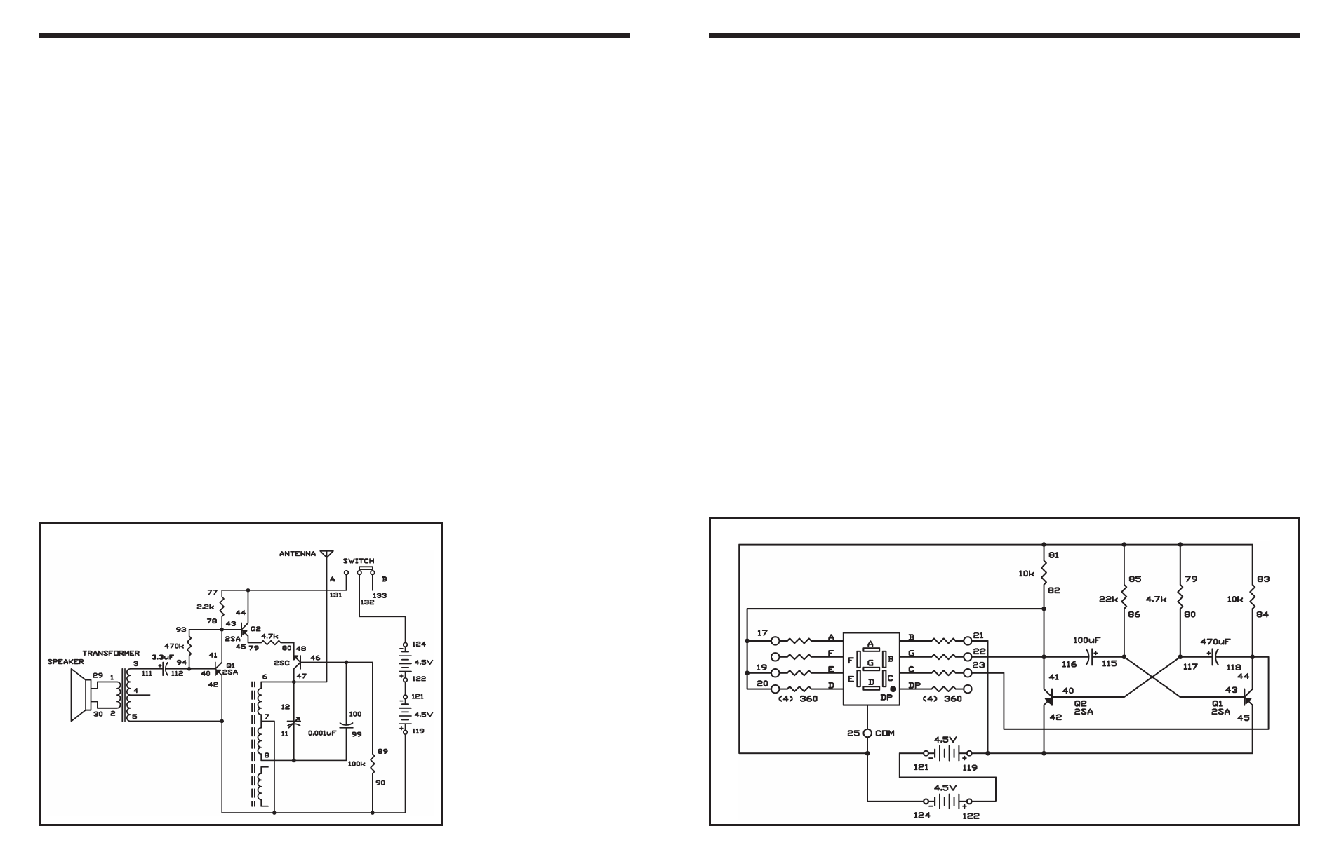
EXPERIMENT #16: FLIP FLOPPING
Wiring Sequence:
o 17-19-20-22-41-116-82
o 21-42-45-119
o 23-44-118-84
o 79-81-83-85-25-124
o 80-117-40
o 86-115-43
o 121-122
Schematic
This AM radio station circuit lets you actually transmit
your voice through the air.
When you completed wiring the circuit, tune your AM
radio a weak station or place with no stations. Place
the AM radio close to the circuit since the signal can
only transmitted a few feet. As you talk into the
speaker adjust the tuning capacitor, until you hear
your voice on the radio
The audio signals produced as you talk into the
speaker are amplified by transistor Q1. These
signals control the amplitude of the RF oscillator
signal. The antenna and tuning capacitor tune the RF
signal to the setting on your AM radio dial and it is
transmitted through the antenna.
The amplitude of the RF signal is controlled by
transistor Q2. The RF signal is amplified by NPN
transistor (part of the RF oscillator) before the AF
(audio frequency) signal modulates it.
Notes:
EXPERIMENT #111: AM RADIO STATION
Wiring Sequence:
o 1-29
o 2-30
o 3-111
o 5-7-90-42-119
o 6-12-47-ANT
o 8-11-99
o 40-112-94
o 41-43-93-78
o 77-44-131
o 45-79
o 89-100-46
o 48-80
o 121-122
o 124-132
Schematic