Experiment #41: “nand” enable circuit using ttl, Experiment #85: voice-controlled led – Elenco 130-in-1 Electronics Playground User Manual
Page 57
-57-
NAND gates are able to act as electronic
guardsmen. If you don’t want a signal to be placed
into input of a circuit, a NAND will make sure that it
doesn’t happen.
In the schematic, one thing that you recognize right
away is the multivibrator. By watching the LED you
can see the multivibrator. You will also realize that the
multivibrator provides one of the inputs to the NAND
gate. With the use of the schematic can you figure
out what occurs when the switch is set to A? B? Are
you able to figure out what occurs when LEDs 1 and
2 do with the switch set to A and then set to B? Make
sure you that you make notes and then compare
them with what you learn.
Set the switch to B, before completing the circuit.
Once you have finished the wiring connect terminals
13 and 14 and then look at LEDs 1 and 2. You will
notice that LED 1 will “blink” in order to indicate the
output of the multivibrator. Look now at the LED 2.
You will find that it is lighting continuously, thus
indicating that something is preventing the LED
signal at 1 from reaching the second LED. Set the
switch to A and then look at LED 1. What is
occurring? Is it the same occurrence that was
happening to both LED 1 and LED 2?
As you can see, LED 1 and LED 2 are taking turns
going on and off. This is because we make one of the
two inputs to the NAND equivalent to 1 once the
switch is set to A. The multivibrator sends 0 and then
signals to the other NAND input. When the output for
the mulitivibrator is 1, then the LED 1 lights but only
because both input signals to the NAND are 1, then
the NAND output is 1 and the LED 2 lights. Now try
to figure out what occurs when the switch is set to B
– why does the LED 2 always light. Hint: B switch
supplies an output of 0.
Now were you able to figure all of that out before you
built the circuit? We sure hope so
☺
Notes:
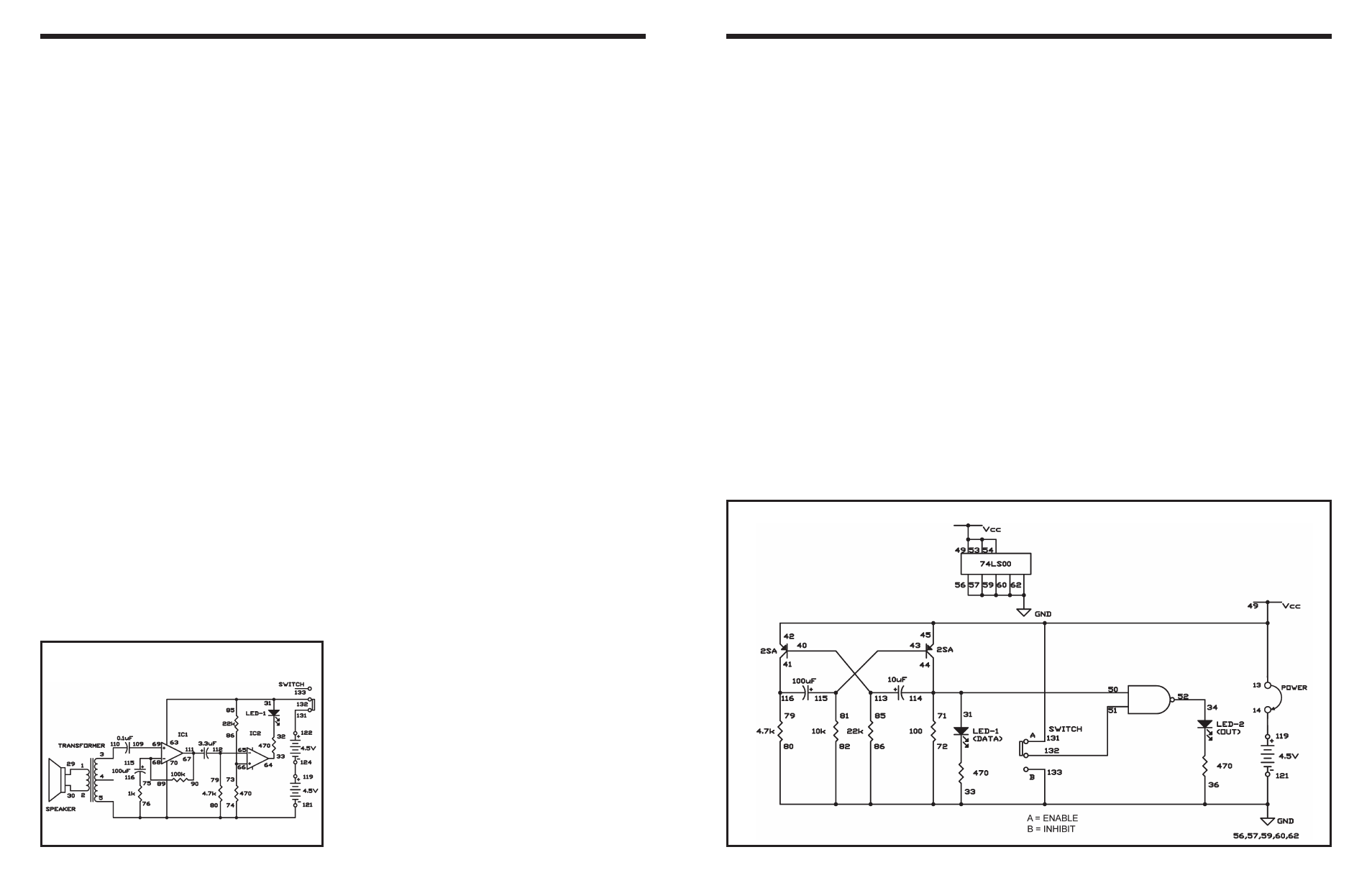
EXPERIMENT #41: “NAND” ENABLE CIRCUIT USING TTL
Wiring Sequence:
o 13-49-53-54-42-45-131
o 14-119
o 71-50-31-44-114
o 86-82-80-72-56-57-59-60-62-33-36-121-133
o 34-52
o 40-113-85
o 41-116-79
o 43-115-81
o 51-132
o 13-14 (POWER)
Schematic
-104-
A microphone can be used to detect sound. Here you
will make a circuit that lights the LED when the
microphone detects sound, using the speaker as a
microphone.
Slide the switch to position B and construct the
circuit. When you finish the wiring, by sliding the
switch to position A to turn on the power. Now talk
into the “microphone” (the speaker) or tap it lightly;
the LED blinks.
Observe the schematic. IC1 is configured as a non-
inverting amplifier with a gain of about 100, and it
amplifies the signal from the microphone (the
speaker). IC2 is configured as a comparator,
comparing the output of IC1 to a reference voltage
from the battery. When IC1’s output exceeds the
reference voltage, the comparator output goes low,
and the LED lights.
Notes:
EXPERIMENT #85: VOICE-CONTROLLED LED
Schematic
Wiring Sequence:
o 1-29
o 2-30
o 3-110
o 5-76-74-80-70-121
o 85-31-63-132
o 33-64
o 79-65-112
o 73-86-66
o 90-67-111
o 89-68-115
o 69-109
o 75-116
o 119-124
o 122-131