Experiment #18: transistor action, Experiment #109: operational amplifier am radio – Elenco 130-in-1 Electronics Playground User Manual
Page 31
-130-
-31-
There are three connections made on a transistor;
one of these (the base) controls the current between
the other two connections. The important rule to
remember for transistors is: a transistor is turned on
when a certain voltage is applied to the base. A
positive voltage turns on an NPN type transistor. A
negative voltage turns on a PNP type transistor.
In this project the LED display shows which transistor
is on by lighting either the top or the bottom half. This
demonstrates how a positive voltage controls an
NPN transistor and the PNP transistor is controlled
by a negative voltage.
After the connections are made the NPN transistor
will be turned on because the positive voltage
through the 1k
Ω resistor is applied to the base. This
turns on the upper half of the LED display.
Simultaneously the PNP is off because current
cannot flow to its base. (The current flows from the
PNP emitter to the NPN transistor base; however,
this flow from the PNP base is blocked by the diode.)
The NPN is turned off if you press the key, because
current is diverted away from its base. The PNP is
turned on simultaneously because now current can
flow from its base through the 4.7k
Ω resistor. As a
result, the upper LED segments turn off and the
lower segments turn on.
Notes:
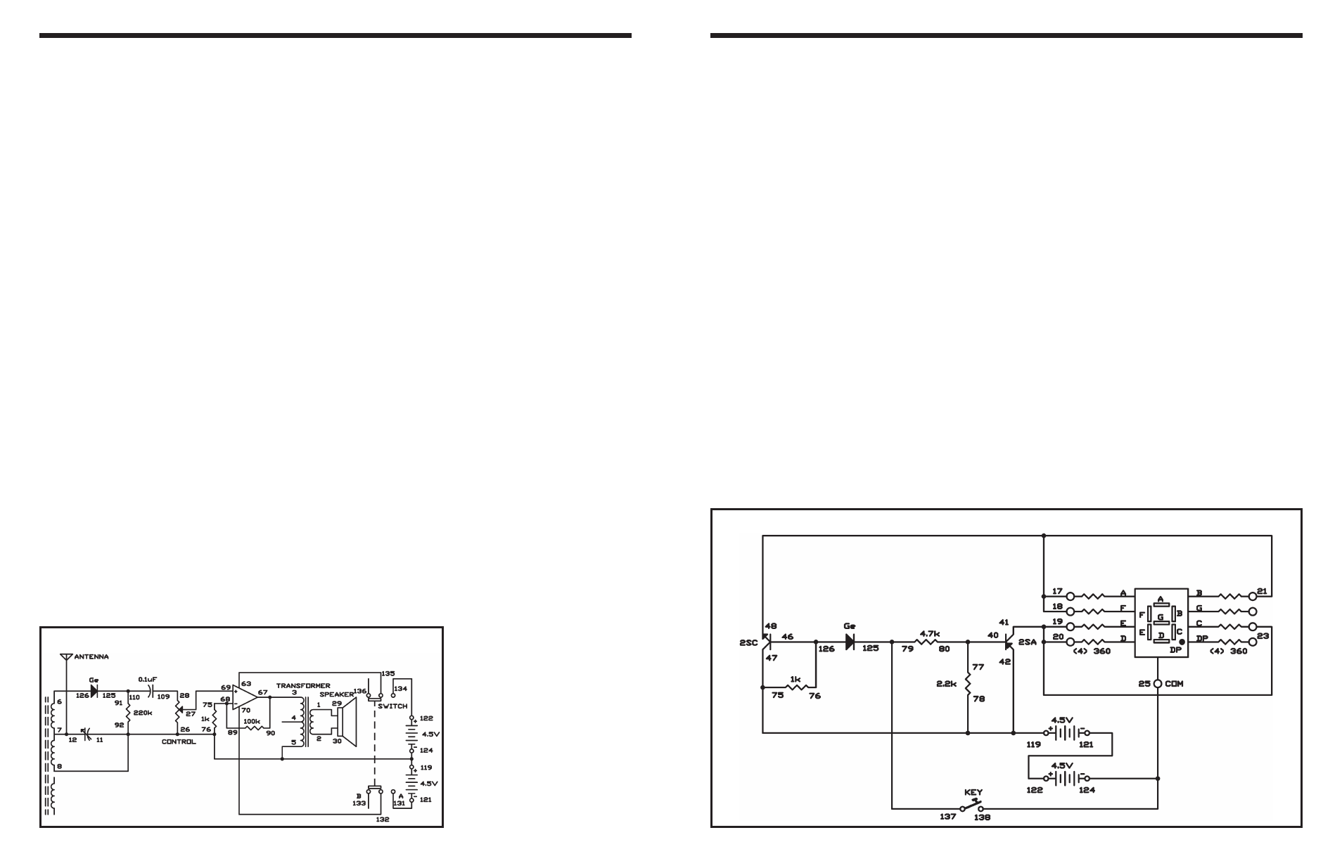
EXPERIMENT #18: TRANSISTOR ACTION
Wiring Sequence:
o 18-17-21-48
o 19-20-23-41
o 25-124-138
o 40-80-77
o 75-78-47-42-119
o 76-46-126
o 79-137-125
o 121-122
Schematic
In emergency situations when there is no power, a
germanium diode radio can be used. Generally they
do not perform well and limited to using and crystal
earphone since they have no power source.
In this circuit, we will use an operational amplifier so
you can hear the radio through the speaker. This
simple IC radio uses the dual operational amplifier as
a two-power source, non-inverting amplifier.
Slide the switch to position B and assemble the
experiment. After wiring the circuits put up the
antenna and connect it to the circuit. Set the control
to the 12 o’clock position and slide the switch to
position A to turn on the power. Turn the tuning
capacitor until you hear a station. You can try picking
up weaker stations, by using the earphone in place of
the speaker in connections to terminals 1 and 2.
Notes:
EXPERIMENT #109: OPERATIONAL AMPLIFIER AM RADIO
Wiring Sequence:
o 1-29
o 2-30
o 3-67-90
o 5-8-11-76-92-26-119-124
o 6-126
o 7-12-ANT
o 27-69
o 28-109
o 63-135
o 68-89-75
o 70-132
o 91-110-125
o 121-131
o 122-134
Schematic