Experiment #49: machiny sound, Experiment #76: miller integrating circuit – Elenco 130-in-1 Electronics Playground User Manual
Page 66
-66-
Listen to the sound this project makes. Take your
time and check your work because there are a lot of
wiring steps. Once you’ve finished, set the switch to
position A. What are you hearing? From looking at
the schematic, can you explain how the circuit
produces this sound?
This circuit has two multivibrators, one with PNP
transistors, and one built with NAND gates. You have
used both types before, but not together in the same
circuit. The NAND gate multivibrator affects the
operation of the transistor multivibrator, which sends
its output through the NPN transistor to the audio
amplifier. You hear the resulting sound from the
speaker.
By substituting a different value for the 470
μF
capacitor, you can change the sound this circuit
makes. See what happens when you try different
values for the 10k
Ω resistor and the 0.05μF
capacitor.
Notes:
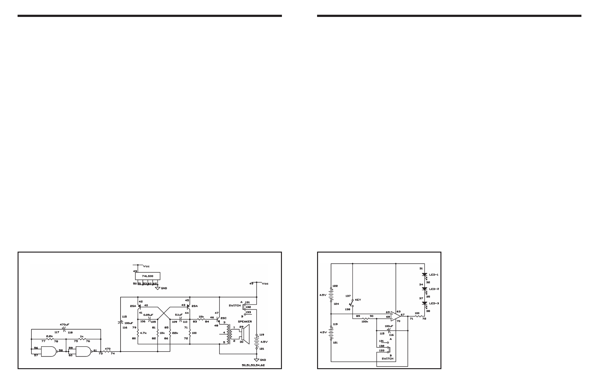
EXPERIMENT #49: MACHINY SOUND
Wiring Sequence:
o 1-29
o 2-30
o 3-48
o 5-50-51-53-54-72-80-62-121
o 40-109-85
o 41-106-79
o 42-45-47-131-115-49
o 43-105-81
o 44-110-83-71
o 46-84
o 57-56-77-117
o 58-59-60-75-78
o 61-73-76-118
o 74-82-86-116
o 119-132
Schematic
-95-
You know that an LED promptly lights when you turn
it on. You can also light it up gradually. In this project,
you’ll be able to observe the LEDs slowly get brighter
while you hold down the key.
This circuit arrangement is called a Miller integrating
circuit. The output of the circuit increases as its input
rises. The integrating circuit increases the value of
the 100
μF capacitor above its actual value. When
you press the key, the LEDs become brighter and the
capacitor charges slowly through resistor R. Setting
the switch to position B discharges the capacitor, and
the LEDs turn off.
Before completing the project, set the switch to
position B, to discharge the capacitor. Set the switch
to position B and hold the key down to watch LEDs
1, 2, and 3 become brighter. In about 5 seconds they
will reach maximum brightness. Now set the switch
to B to discharge the capacitor, then hold down the
key to do the experiment again.
Notes:
EXPERIMENT #76: MILLER INTEGRATING CIRCUIT
Schematic
Wiring Sequence:
o 31-63-122-137
o 32-34
o 35-37
o 38-72
o 71-67-116-133
o 68-90-115-132
o 69-124-119
o 70-121
o 89-138