Experiment #52: monster mouth, Experiment #73: inverting dual supply op amp – Elenco 130-in-1 Electronics Playground User Manual
Page 69
-69-
Do you know of someone who is a big mouth? (Or,
have you ever been accused of being one?) This
experiment lets you and your friends see who’s got
the most ear-splitting voice.
How does this work? When you yell, you create
sound waves, which are actually variations in air
pressure. These air pressure variations create
pressure on the crystalline structure in the earphone.
In a crystal structure, pressure creates voltage
through a process called piezoelectricity. The voltage
produced by the earphone is applied to a two-
transistor circuit, which amplifies it. You can use the
control to adjust the amount of the signal from the
earphone that is amplified. Two NAND gates in
series control the lighting of LED 1.
Set the switch position A and set the control to
position 5. Watch LED 1 as you yell into the
earphone; it probably lights. To make it more difficult
to light LED 1, try turning the control counter-
clockwise. (Try adjusting it just a tiny bit each time.)
See how far you can lower the control to reduce the
strength of the amplifier and still light the LED.
Notes:
EXPERIMENT #52: MONSTER MOUTH
Wiring Sequence:
o 27-79
o 28-110
o 124-131-31-49
o 33-55
o 41-43-100-81
o 42-72
o 44-109-99-83
o 45-88-78
o 46-80
o 47-115-51-50
o 52-53-54
o 77-71-123
o 119-132
o 40-87-13-EARPHONE
o 121-26-48-116-62-60-59-57-56-84-82-14-EARPHONE
Schematic
-92-
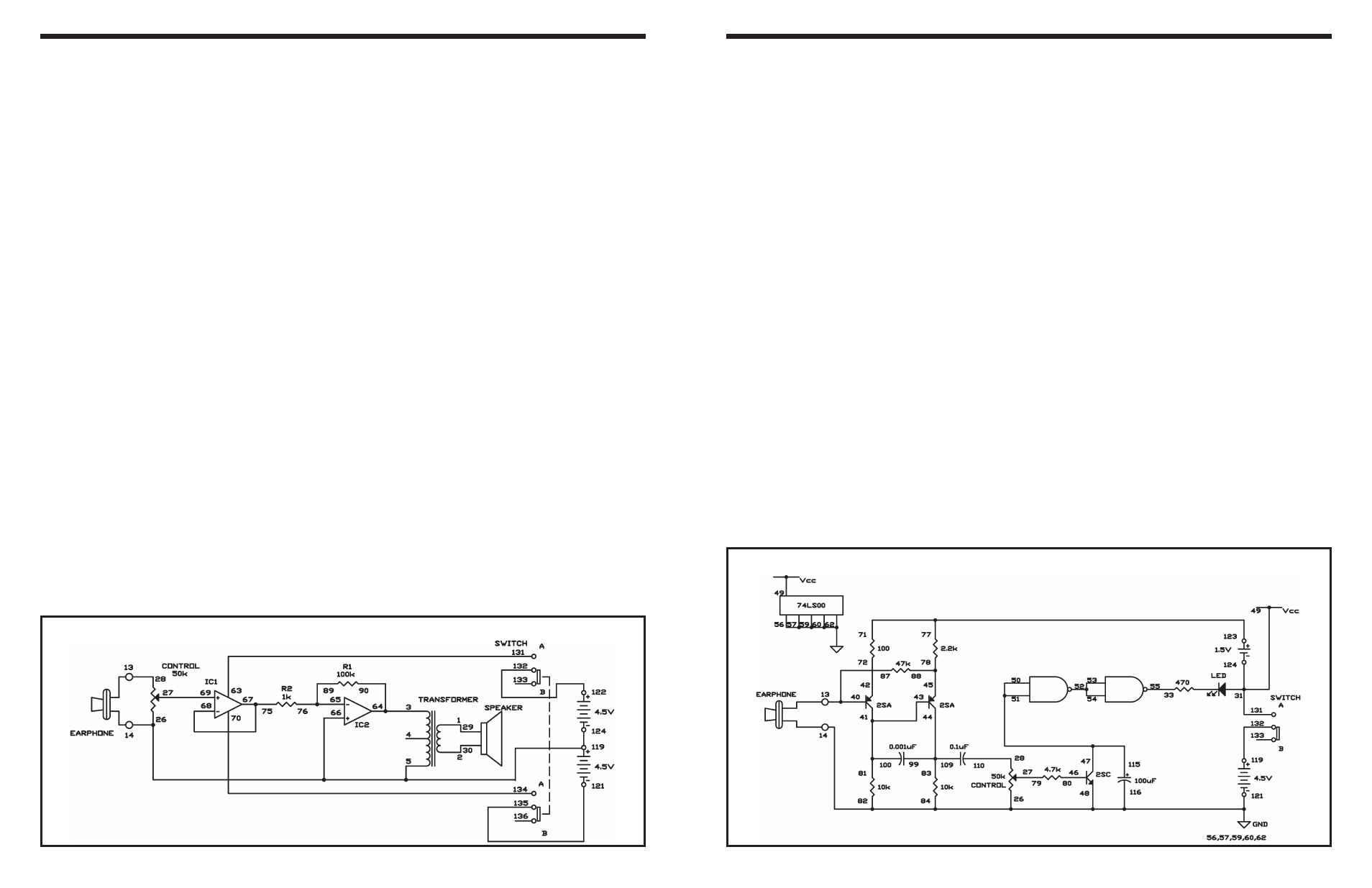
This is another two-power source microphone
amplifier, but this one is an inverting amplifier. You
will use the earphone as a microphone again.
Slide the switch to position B and construct the
circuit. Once you finish the wiring, slide the switch to
position A to turn the power on, adjust the control
clockwise, and speak into the “microphone” – the
earphone. This project works just like the preceding
one.
IC 2 is an inverting amplifier and IC 1 is used as a
buffer between the earphone and IC2, and has a
gain of 1. IC2 is an inverting amplifier, with the input
applied through its negative (–) terminal, not the
positive (+) one as in our last project. IC2’s gain is
about 100, as determined by:
R1/R2 = 100k/1k=100.
If you increase R1 or decrease R2, the gain becomes
larger. See what occurs to the gain when you alter
the value of R2 to 470.
Notes:
EXPERIMENT #73: INVERTING DUAL SUPPLY OP AMP
Wiring Sequence:
o 1-29
o 2-30
o 3-64-90
o 27-69
o 63-131
o 65-89-76
o 68-67-75
o 70-134
o 121-135
o 122-132
o 124-119-26-66-5-14-EARPHONE
o 28-13-EARPHONE
Schematic