Experiment #2: police siren, Experiment #126: resistance tester – Elenco 130-in-1 Electronics Playground User Manual
Page 13
-148-
-13-
Here is the first siren you are going to do – don’t be
shocked if this experiment becomes the most famous
circuit in this kit.
This siren sounds like a real siren on a police car!
After the wiring is competed press the key. The tone
you eventually hear gets higher after pressing the
key. When you release the key, the tone gets lower
and then fades out.
Try some of these modifications:
1. If you change the 10
μF capacitor to a 100μF or a
470
μF it will give a very long delay for both turn
off and turn on.
2. Change the circuit to remove the delays by
temporarily disconnecting the 10
μF capacitor.
3. Change out the 0.02
μF capacitor to a 0.01μF
capacitor, and then to a 0.05
μF capacitor.
Notes:
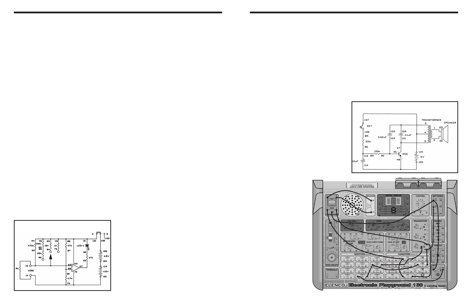
EXPERIMENT #2: POLICE SIREN
Wiring Sequence:
o 1-29
o 2-30
o 3-103-109
o 4-119-137
o 5-47-110
o 46-104-90
o 114-48-120
o 85-138
o 86-89-113
If you use a meter you can find the exact value of a
resistance; but when you only want to know
approximate resistance values, you can use this
resistance tester.
This circuit converts resistance to electric current and
compares it with the comparator’s reference current
to tell you the approximate range of resistance. The
comparator has a reference voltage of about 0.82V.
Build the circuit and set the switch to position A.
Connect the material to be tested between terminals
13 and 14. The LED lights if the resistance is less
than 100k
Ω, otherwise it is off. If the LED lights,
connect terminals 93 and 86. If the LED turns off now
the resistance is between 10
Ω and 100kΩ. If it stays
on, remove the wire from terminal 86 and connect it
to terminal 84. If the LED turns off now, the
resistance is in the range of 1 to 10k
Ω. If the LED still
doesn’t turn off, remove the wire from terminal 84
and connect it to terminal 76. If the LED turns off
now, it means that the resistance is in the range of
100
Ω to 1kΩ; if it stays on, the resistance is less than
100
Ω.
Notes:
EXPERIMENT #126: RESISTANCE TESTER
Schematic
Wiring Sequence:
o 13-93-69-WIRE
o 14-79-70-121
o 75-83-94-90-88-31-63-131
o 33-67
o 68-80-87
o 85-89
o 119-124
o 122-132
Schematic