Vi. meet transistor-transistor logic, Experiment #78: operational amplifier blinking led – Elenco 130-in-1 Electronics Playground User Manual
Page 64
-64-
VI. MEET TRANSISTOR-TRANSISTOR LOGIC
-97-
Now you’re going to make a blinking LED circuit
using an operational amplifier. In this experiment, an
LED continuously lights and turns off slowly.
Slide the switch to position B and connect the wires
for this circuit. When you finish connecting the
project, slide the switch to position A to turn on the
power. After a couple seconds, you’ll see the LED
start to blink. Watch carefully and you should be able
to observe that it’s on and off periods are about
equal.
The operational amplifier works as an astable
multivibrator at low frequency. You can alter the
period of oscillation (the LED blinking rate) by using
different values for R and C. See what happens to
the blinking rate when you make the value of R
220k
Ω.
One last thing - the operational amplifier has high
input resistance at its inputs - so there is very little
current flowing into its inputs. This means you can
operate it to build accurate blinkers and timers with
longer intervals.
Notes:
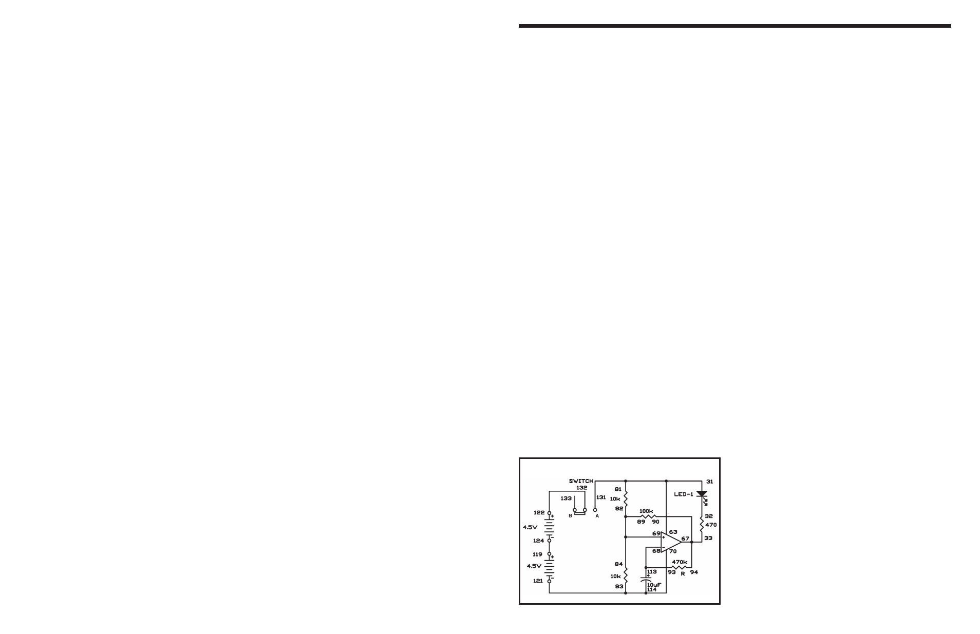
EXPERIMENT #78: OPERATIONAL AMPLIFIER BLINKING LED
Schematic
Wiring Sequence:
o 81-31-63-131
o 33-67-90-94
o 93-68-113
o 69-82-84-89
o 83-70-114-121
o 119-124
o 122-132