Experiment #10: sound effects for horror movies, Experiment #118: rf signal tracer – Elenco 130-in-1 Electronics Playground User Manual
Page 21
-140-
-21-
The sounds that you will hear from this circuit will
remind you of the music you hear in horror movies.
Once you wire the project, use your special light
shield and your hand to change the light amount that
shines onto the CdS cell. This changes the pitch of
the music.
The pitch of a sound is determined is by the sound
wave’s frequency, which is the number of cycles of
electromagnetic energy per second. The amount of
light on the CdS cell determines the resistance of the
cell. The more resistance you have the slower the
frequency of the musical sound waves. The oscillator
circuit produces the basic sound wave.
Frequency modulation, or FM, is when the frequency
of an oscillator is controlled by part of the circuit. An
FM radio signal is similar to this but at higher
frequencies.
Notes:
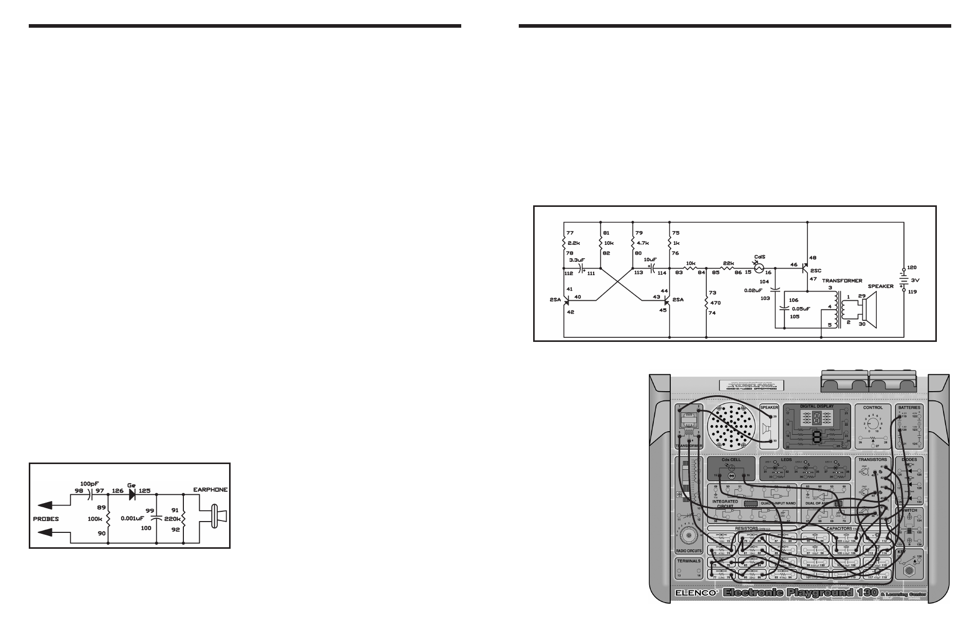
EXPERIMENT #10: SOUND EFFECTS FOR HORROR MOVIES
Wiring Sequence:
o 1-29
o 2-30
o 3-47-106
o 4-74-45-42-119
o 5-103-105
o 15-86
o 16-46-104
o 40-113-80
o 41-112-78
o 44-114-83-76
o 120-48-81-79-75-77
o 73-85-84
Schematic
This experiment is a wide band, untuned RF signal
tracer. You can use it to check for antenna signals
and find sources of RF noise and interference. This
circuit is like an untuned crystal set.
The 100pF capacitor in the input blocks DC and the
60Hz power line frequency, so the wires can touch
almost anywhere without fear of electrical shock. Of
course, you should never intentionally probe around
high voltage.
Attach the probes between grounded objects and
other metallic objects that can act as antennas. You
will find that this circuit allows you to receive all kinds
of AM signals as well as noise. For example, if you
have citizens’ band transmitters, you can hear these
signals if the transmitter is close enough to the signal
tracer.
Sometimes you might hear noise from fluorescent
lights, auto ignition systems, light dimmers, or
switches opening and closing.
Notes:
EXPERIMENT #118: RF SIGNAL TRACER
Schematic
Wiring Sequence:
o 89-97-126
o 90-92-100-EARPHONE-PROBES
o 125-99-91-EARPHONE
o 98-PROBES