Experiment #20: transistor switching, Experiment #108: cooking timer – Elenco 130-in-1 Electronics Playground User Manual
Page 33
-128-
-33-
In this experiment you study the switching action of
transistors in turning an LED on. You will be using
two different transistors - one of the two PNP types
and the NPN type included in your kit. PNP and the
NPN refers to the arrangement of the semiconductor
materials inside the transistors.
The NPN transistor at the bottom of the schematic
stays on due to the 47k
Ω resistor supplying voltage
to its base. Making the connection through the 22k
Ω
resistor causes the PNP transistor at the top of the
schematic to turn on.
The resistance of the 22k
Ω is approximately half of
that of the 47k
Ω resistor, so the current supplied to
the base of the PNP transistor is about twice that of
the NPN. Therefore the PNP is turned on “greater”
than the NPN.
Connect the circuit and then press the key: 1 is
displayed. To increase the base current for the NPN
transistor, you have to decrease the value of the
47k
Ω resistor connected to the base – terminal 46.
To do this simply disconnect between 87 and 88 and
then replace them with connections to another
resistor. For example, change connection 87-42 to
83-42 and connection 46-88 to 84-46, to change the
47k
Ω to a 10kΩ resistor. Every time that you lower
the resistor value more current is then supplied to the
base of the transistor, and the LED display lights a
little brighter when you press the key. If you decrease
the resistance below 1k
Ω the transistor may burn
out.
Next, change the resistors to 10k
Ω and then press
the key. Use terminals 83 and 84 and terminals 81
and 82. With the transistors both fully on the
brightness should not change much. If change does
occur check your batteries.
Notes:
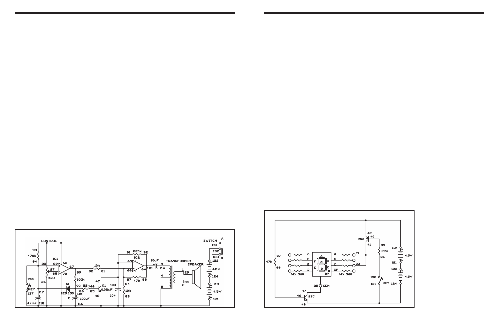
EXPERIMENT #20: TRANSISTOR SWITCHING
Wiring Sequence:
o 21-23-41
o 25-47
o 40-85
o 87-42-119
o 46-88
o 124-48-137
o 86-138
o 121-122
Schematic
Wouldn’t you like to make a kitchen timer that you can
use for cooking meals? This circuit gives out a buzzer
sound for 1 to 2 seconds and automatically stops.
Slide the switch to position B, build the circuit, and set
the switch to position A to turn it on. Set the control
to position 2 on the dial, and press the key to start the
timer. After about 40 seconds, the timer sounds for 1
to 2 seconds and stops. Use the graph you made in
project 107 to preset this timer.
Look at the schematic. When the preset time is up,
the comparator (IC 2) sends out an output. After a
time lag of 1 to 2 seconds produced by R and C, the
transistor Q1 turns on to stop the multivibrator. The
silicon diode discharges C and restores the circuit to
the original state when the timer is restarted.
Notes:
EXPERIMENT #108: COOKING TIMER
Wiring Sequence:
o 1-29
o 2-30
o 3-114
o 5-83-70-104-116-118-137-48-26-121
o 27-68
o 93-63-28-131
o 46-85
o 91-103-65-47
o 92-88-64-113
o 81-84-87-66
o 67-82-89
o 69-94-117-138-129
o 86-90-115-130
o 119-124
o 122-132
Schematic