Experiment #35: “inverter” gate using ttl, Experiment #91: op amp metronome – Elenco 130-in-1 Electronics Playground User Manual
Page 51
-51-
A circuit that has an output that is the opposite of its
input is called an inverter. If the output is 0, (low) then
the input is 1 (high). If the output is 1, then the input
is 0.
Before completing this project set the switch to A.
Next, connect terminals 13 and 14. You’ll observe
that both LED 1 and LED 2 are off. Since the input is
1, the output has to be 0. When you set the switch to
B, you will see both LEDs come on, indicating the
input is 0.
You can see from the schematic that we use two of
the four NAND gates in the IC. With the switch at A,
both inputs to the two NANDs are 1. This means the
outputs of both NANDS are 0 (and the LEDs go out).
When the switch is set to B, the LEDs come back on
because we no longer have all inputs at 1.
One extraordinary thing to think about is how big the
RTL and DTL circuits were in earlier projects. Four
of those circuits, Believe it or not, have been shrunk
down to fit inside this tiny IC.
ICs can be very complex. Large-scale integration
(LSI) is the process of putting several circuits inside
just one IC. The microprocessors running computers
and cell phones are very complex ICs.
Notes:
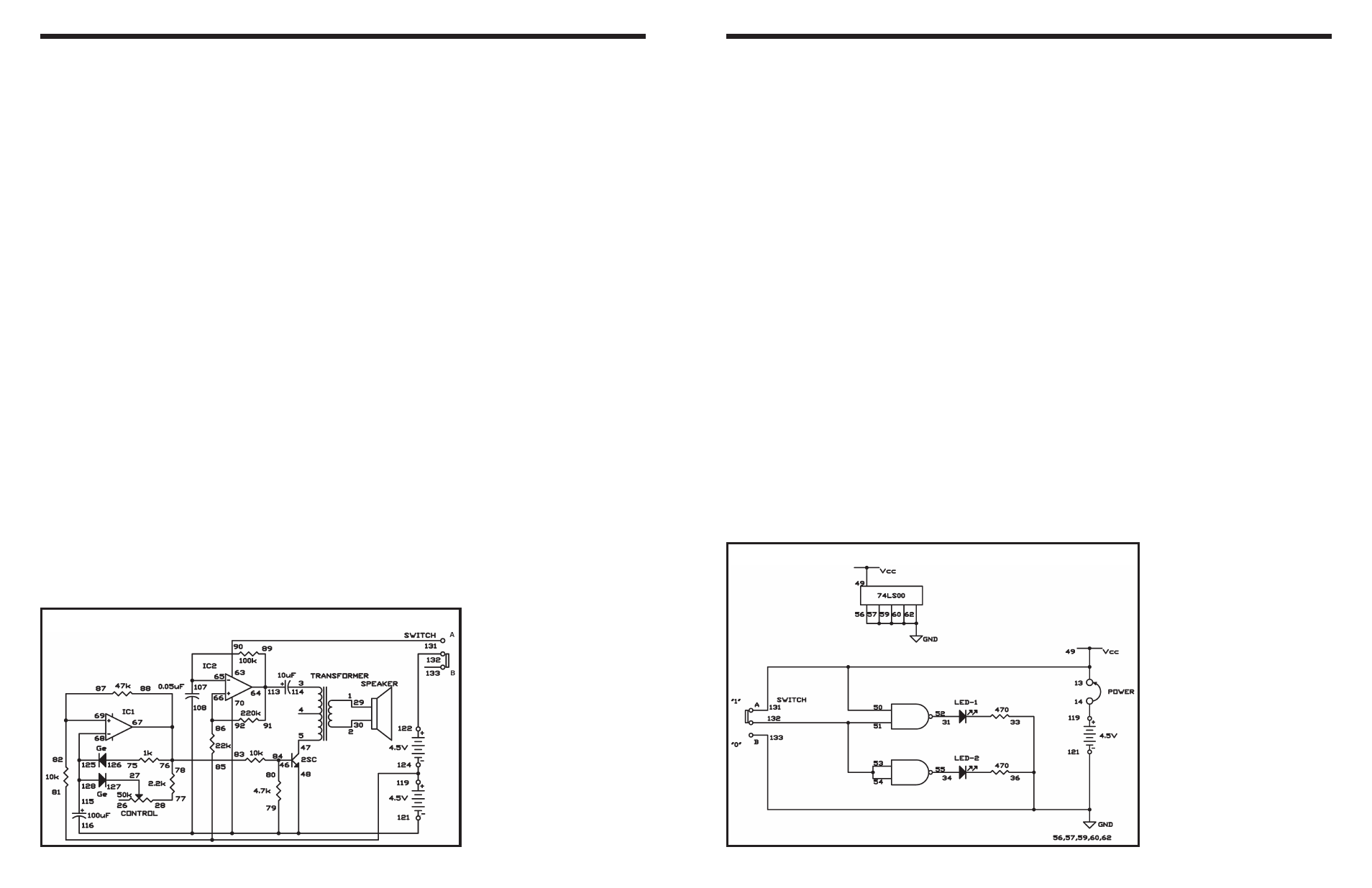
EXPERIMENT #35: “INVERTER” GATE USING TTL
Wiring Sequence:
o 13-49-50-131
o 14-119
o 31-52
o 36-33-56-57-59-60-62-133-121
o 34-55
o 51-53-54-132
o 13-14 (POWER)
Schematic
-110-
This is the operational amplifier version of the
electronic metronome from Project 3 (“Electronic
Metronome”). Slide the switch to position B, and
connect the wires carefully - this project is more
intricate than most of the others. When you complete
assembling the circuit, set the control to the 12
o’clock position, and slide the switch to position A to
turn on the power. You’ll hear a pip noise from the
speaker at fixed intervals. Now gradually rotate the
control clockwise, and the beats come faster.
Now observe the schematic. IC 1 and IC 2 are used
as astable multivibrators, as in our last experiment.
But you’ll notice that IC 1 uses diodes to generate
short pulses and the control is used to modify the
speed of the pulses. The transistor turns on each
time a pulse is generated, and creates a sound.
Notes:
EXPERIMENT #91: OP AMP METRONOME
Wiring Sequence:
o 1-29
o 2-30
o 3-114
o 5-47
o 27-127
o 28-77
o 46-80-84
o 79-70-108-116-48-121
o 63-131
o 89-91-113-64
o 65-90-107
o 86-92-66
o 78-76-83-88-67
o 68-115-125-128
o 82-87-69
o 75-126
o 85-81-119-124
o 122-132
Schematic