Suggestions to help, Troubleshooting – Elenco 130-in-1 Electronics Playground User Manual
Page 10
-151-
-10-
SUGGESTIONS TO HELP
Keep a Notebook
As you’re about to find out, you are going to learn
many things about electronics by using this kit. As you
learn, many of the things you discover in the easy
projects will be built upon in later projects. We suggest
using a notebook to help you organize the data you
will be collecting.
This notebook does not have to be like the one you
use in school. Think of it more as a fun notebook, that
way you can look back on the all the projects you have
done once you finish.
Wiring Sequence Marking
When you are wiring a project, especially those with
lots of connections, you will find it helpful to mark off
each terminal number as you connect the wires to it.
Use a pencil and make light marks so that you can go
back multiple times and re-read the sequence.
Collecting Components
You should start to make your own collection of
electronic parts and therefore have your own scrap
box of electronic parts. You can build your own circuits
in or on top of a framework, box or container. You
could use your circuit as a Science Fair project at
school and even make a major research project from
it.
TROUBLESHOOTING
You should have no problem with the projects working
properly if you follow the wiring instructions. However,
if you do encounter a problem you can try and fix it by
using the following troubleshooting steps. These steps
are comparable to those steps that electronic
technicians use to troubleshoot complex electronic
equipment.
1. Are the batteries being used new? If they are not,
this may be your problem because the batteries
could be too weak to power the project.
2. Is the project assembled properly? Check all the
wiring connections to make sure that you have all
the terminals wired correctly. Sometimes having
someone else look at it helps to find the problem.
3. Are you following the schematic diagram and the
explanation of the circuit? As your understanding
and knowledge expands of electronics, you will be
able to troubleshoot by following only a schematic,
and once you add the description of the circuit you
will be able to figure out your own problems.
4. If you have VOM, try taking some measurements
of the voltage and current. You might be surprised
just how handy a VOM really is.
5. Try building project 24 (Digital Display Circuit for
the Seven-Segment LED). This is a very simple
circuit that lights part of the LED display using only
2 wires.
Contact Elenco
®
if you still need help.
In this experiment, you build and study a low-distortion
sine wave oscillator. Build this experiment after you
have built and studied the previous experiment
because this one has no transformer; transformers
are likely to cause distortion because of their non-
linear characteristics.
As in the previous experiment, you should listen to the
tone of this oscillator and modify the control for the
clearest-sounding single tone (the one with the least
distortion). Again, start with the control near
maximum. The operating frequency is about 300Hz at
the minimum distortion setting of the control.
We call this circuit an RC phase shift oscillator, and it
is considered a basic sine wave oscillator. The positive
feedback of the signal causes oscillations to occur.
The resistors (R) and capacitors (C) make up the path
for the signal to the transistor base. Every time the
signals pass the RC circuits, a slight time lag occurs.
In other words, the rise and fall of the wave (the
phase) shifts slightly. That’s why we call it phase shift.
After the signal has traveled through the circuit, the
phase shifts 180 degrees. When the collector voltage
rises, this rise is fed back to the collector with the
phase shifted. When the base voltage rises, the
collector voltage falls. This repeating cycle causes the
transistor to oscillate.
The frequency changes when you change the control
setting, because the degrees of phase shift changes.
The tonal quality also changes. Set the control to the
point where you can hear the purest tone; at this point
a clear sine wave is generated.
Notes:
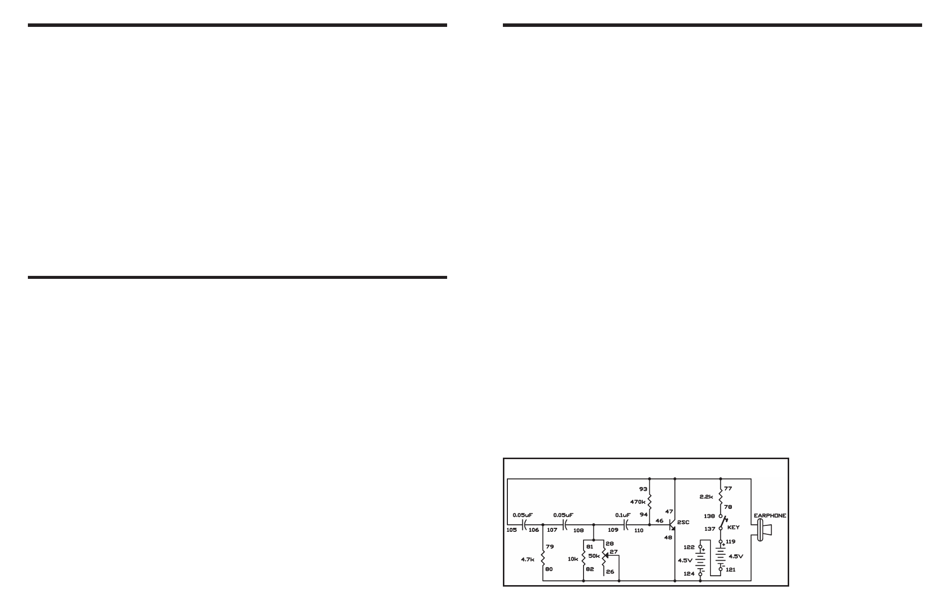
EXPERIMENT #129: SINE WAVE OSCILLATOR WITH LOW DISTORTION
Wiring Sequence:
o 124-27-48-82-80-EARPHONE
o 47-105-93-77-EARPHONE
o 81-109-108-28
o 94-110-46
o 78-138
o 79-106-107
o 119-137
o 121-122
Schematic