Experiment #22: amplify the sound, Experiment #106: op amp three-input “and” gate – Elenco 130-in-1 Electronics Playground User Manual
Page 35
-126-
-35-
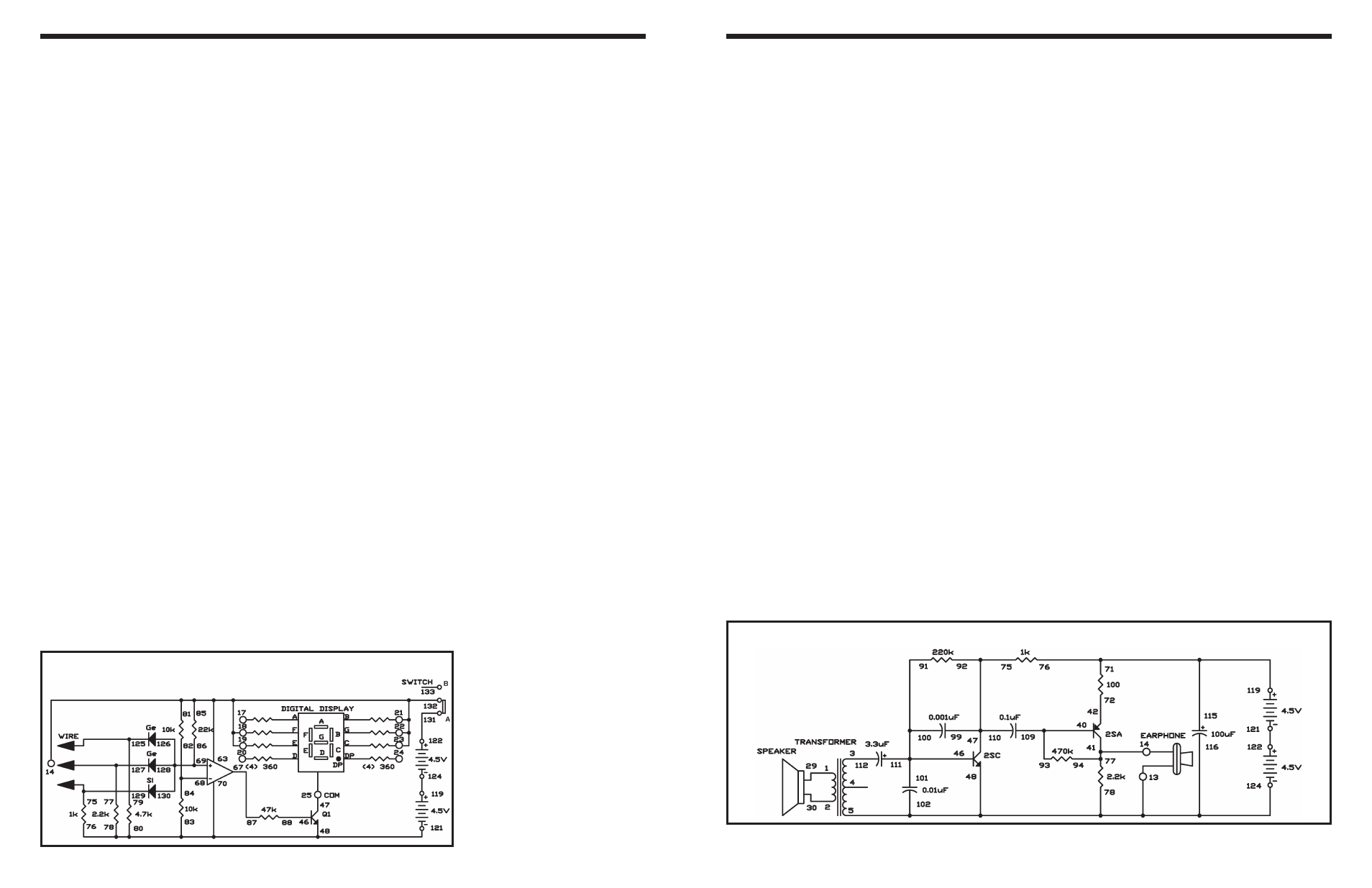
A two-transistor amplifier is used in this circuit. In an
amplifier, a small signal is used to produce or control
a large signal. This circuit is similar to an early model
transistor hearing aid amplifier.
Your kit’s speaker can change sound pressure into a
weak voltage. The transformer increases the voltage,
and which is then applied to the NPN transistor
through the 3.3
μF capacitor.
Now it is time to talk about the transformer. The
transformer has a copper wire wound hundred of
turns. We call this a coil. A transformer has two coils
separated by an iron plate.
A magnetic field is created when electricity flows
through a coil. The reverse is also true - if a coil is
subjected to a change in its magnetic field strength,
electricity flows through it. The magnetic field created
depends on the number of windings in the coil, so
when electricity flows through the first coil (the
primary coil), the voltage at the second coil (the
secondary coil) will be different if the number of
windings is different. Induction is the creation of an
electric charge using a magnetic field. Now go back
to project 17 and think of how a large voltage is
induced at the secondary side when 9V is applied to
the primary side of the transformer.
Notes:
EXPERIMENT #22: AMPLIFY THE SOUND
Wiring Sequence:
o 1-29
o 2-30
o 3-112
o 5-124-48-116-102-78-13-EARPHONE
o 93-109-40
o 41-94-77-14-EARPHONE
o 42-72
o 91-100-101-111-46
o 75-92-99-110-47
o 71-76-115-119
o 121-122
Schematic
Who says an operational amplifier (op amp) can’t be
used to make a digital circuit? Here, you will use one
to make an AND gate. The LED display is the output
device. If it displays nothing, at least one of the output
signals is logical 0 or low; if it displays H, they are all
logical 1 or high.
When you finish the wiring, turn on the power by
setting the switch to position A. The LED remains
dark. The input terminals are 125, 127, and 129.
These terminals are connected to the negative (–)
terminal, so they do not cause the LED to light.
Terminal 14 is connected to the positive (+) terminal,
so it is the logic 1 terminal. When you connect
terminals 125, 127, and 129 to terminal 14 in various
combinations, you see that the LED lights and shows
H only when terminals 125, 127, and 129 are all
connected to terminal 14 - logic 1.
Notes:
EXPERIMENT #106: OP AMP THREE-INPUT “AND” GATE
Wiring Sequence:
o 14-85-81-63-19-18-21-22-23-132
o 25-47
o 46-88
o 78-76-83-80-70-48-121
o 67-87
o 68-82-84
o 86-69-126-128-130
o 129-75-WIRE
o 127-77-WIRE
o 125-79-WIRE
o 119-124
o 122-131
Schematic