Experiment #3: metronome, Experiment #125: pulse tone generator – Elenco 130-in-1 Electronics Playground User Manual
Page 14
-147-
-14-
Learning to play a musical instrument? Then you
might find this experiment helpful. This is an
electronic version of the metronome, used by musical
students and musical geniuses alike, worldwide.
If you press the key, you hear a repeating sound from
the speaker. Turn the control knob to the right and
you’ll hear the sound “get faster” as the time between
sounds shortens.
Try swapping out the 4.7k
Ω resistor with different
one. Also, you might want to try a different capacitor
in place of the 100
μF capacitor too see what effect it
will have. Are you still keeping notes?
If you would like to hear the difference that a stronger
capacitor makes, try connecting the 470
μF capacitor
to the batteries. Connect terminal 117 to 119 and
terminal 118 to terminal 120. You might need to
adjust the control to maintain the same pulse rate.
Notes:
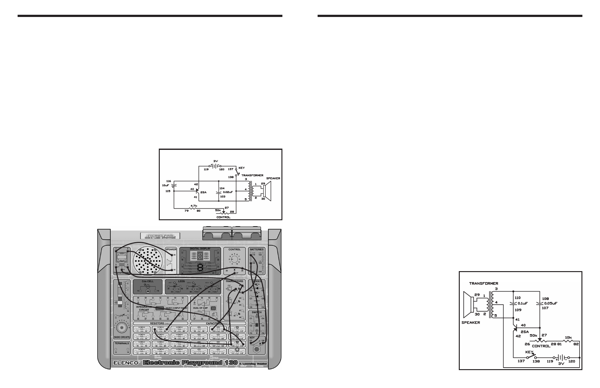
EXPERIMENT #3: METRONOME
Wiring Sequence:
o 1-29
o 2-30
o 3-104-116
o 4-28-138
o 5-41-103
o 27-80
o 40-115-79
o 42-119
o 120-137
Schematic
This experiment is a pulse-tone oscillator with an
adjustable frequency that can obtain a wide range of
notes. You can play tunes on it that sound like an
electronic organ, but it takes some practice.
To play a tune, modify the control to the proper note
and press the key. Readjust the control for the next
note and press the key again.
When you close the key the first time, the base
current flows around the loop formed by the battery,
the 10k
Ω resistor, the 50kΩ resistor, the transistor
base and emitter, and the key.
The base current causes the collector current to flow
around the loop formed by the 3V supply, the lower
half of the transformer winding, the transistor
collector and emitter, and the key.
The current through the transformer causes a current
to flow around the loop formed by the top transformer
winding, the 0.05
μF capacitor, the transistor base
and emitter, the key, the battery and back to the
transformer’s center terminal (terminal 4). This
current quickly (in less than 0.0001 seconds)
charges the 0.05
μF to about 4V or so with a polarity
negative on the transformer side and positive on the
transistor base lead side. The speaker is only
activated while the current flows in the transformer.
When the induced voltage from the top half of the
transformer winding stops, the charging of the
0.05
μF capacitor stops, then the capacitor begins to
charge again. As soon as the discharge begins, the
capacitor voltage becomes higher than the battery
voltage. The reverse polarity voltage is applied to the
base and the transistor turns off. Now, all transistor
junctions act as open circuits. The capacitor
discharges around the loop formed by the top
transformer winding, the 10k
Ω resistor, and the 50kΩ
resistor. When you reduce the control setting, the
discharge is faster, so the process is repeated at a
faster rate causing a higher frequency. The cycle
repeats when the 0.05
μF capacitor discharges to
slightly below the 3V of the battery.
Notes:
EXPERIMENT #125: PULSE TONE GENERATOR
Schematic
Wiring Sequence:
o 1-29
o 2-30
o 3-108-110
o 4-82-120
o 27-40-107
o 28-81
o 5-41-109
o 42-137
o 119-138