A major change, Experiment #113: two-transistor radio – Elenco 130-in-1 Electronics Playground User Manual
Page 27
-134-
-27-
Until now, in addition to the wiring sequences you have
had drawings to help guide you in the wiring connections.
The rest of the projects will have just the schematic
diagram without the circuit drawings.
A schematic diagram is like a road map but it is used for
electronic circuits. It shows you how different parts connect
together and how electricity flows through a circuit.
Electronics engineers and technicians use schematics to
help guide them through circuits.
You don’t need to build your circuits from the schematic
diagrams by themselves. We have added the number of
terminals to where you will be making the wiring
connections on each schematic, to help you out - a line
between numbers on the schematic means that you
should connect a wire between those terminals in your kit.
Every part in your kit has a schematic symbol all of its
own. At the beginning of this manual you will find a picture
of each part with its schematic symbol as well as a short
description.
As you will start to notice, the schematics have some lines
that cross each other and that there is a dot at the crossing
point. This means that the two wires which are
represented by the lines, are to be connected at the point
where the dot is located (you will find the terminal number
next to the dot). If there is not a dot where the lines cross,
this means that the wires do not connect (you won’t see a
terminal number if the wires don’t cross).
Lines Are Connected / Lines Not Connected
The schematic diagrams will look confusing at first but
they are simple once you have some practice using them.
Don’t get discouraged if you get confused at first. You will
be constructing circuits in no time by just looking at the
schematic diagrams.
To be able to read schematic diagrams is important for
anyone getting into the field of electronics. Many
electronics books and magazines display intricate circuits
only in schematic form. A schematic is also shorter and
more accurate way to show a circuit rather than a written
form.
A MAJOR CHANGE
This radio circuit uses two-transistor receiver with
enough gain (amplification) to drive the speaker.
These simple radios require a good antenna and
ground system. Wire the circuit and use terminal 74
as the ground terminal. Connect the antenna to
terminal 95 or 97. Use the one that gives the best
results.
The radio’s detector circuit uses a diode and 22k
Ω
resistor. First, try to use the radio without the 22k
Ω
resistor by disconnecting the wire from terminal 85.
The results are ________ (worse / improved) for
weak stations and ________ (worse / improved) for
strong stations.
The basic rules of radio reception are the same as
in the last experiment (“Crystal Set Radio”). The
tuning capacitor selects the radio station frequency.
The diode and 0.02
μF capacitor rectify (detect) the
audio signal, changing it from AC to DC. Since these
signal are very week and must be amplified, so you
can hear it through the speaker. Transistor Q1
amplifies the signal first, then the control adjusts the
volume, and finally Q2 amplifies the signal again.
Finally, the speaker produces the amplified sounds.
Notes:
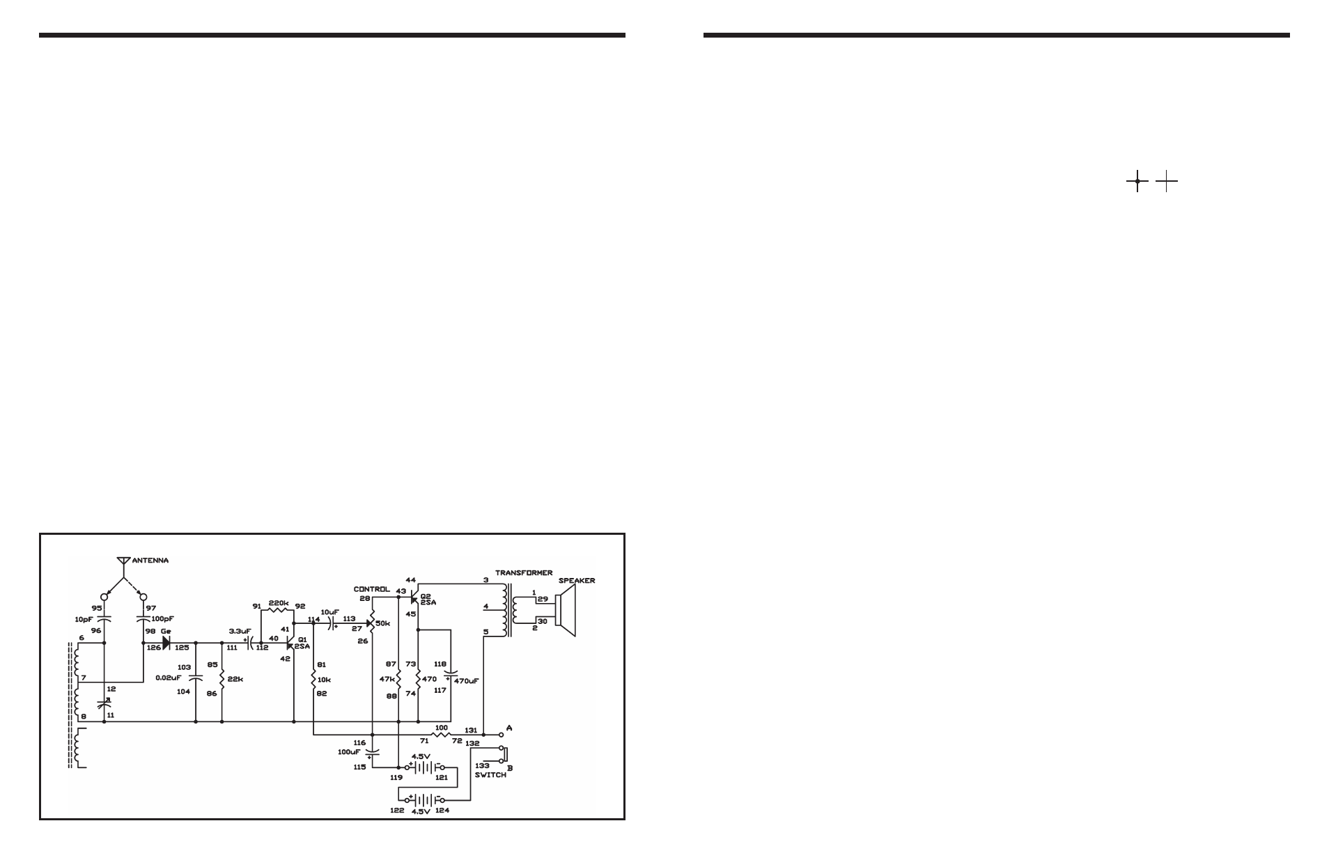
EXPERIMENT #113: TWO-TRANSISTOR RADIO
Wiring Sequence:
o 1-29
o 2-30
o 3-44
o 5-72-131
o 6-12-96
o 7-98-126
o 8-11-74-86-88-104-115-117-42-119
o 71-82-116-26
o 27-113
o 28-43-87
o 40-112-91
o 81-92-114-41
o 45-118-73
o 85-103-111-125
o 121-122
o 124-132
o 95-ANT (or 97-ANT)
Schematic