Experiment #118: rf signal tracer – Elenco 130-in-1 Electronics Playground User Manual
Page 140
-140-
This experiment is a wide band, untuned RF signal
tracer. You can use it to check for antenna signals
and find sources of RF noise and interference. This
circuit is like an untuned crystal set.
The 100pF capacitor in the input blocks DC and the
60Hz power line frequency, so the wires can touch
almost anywhere without fear of electrical shock. Of
course, you should never intentionally probe around
high voltage.
Attach the probes between grounded objects and
other metallic objects that can act as antennas. You
will find that this circuit allows you to receive all kinds
of AM signals as well as noise. For example, if you
have citizens’ band transmitters, you can hear these
signals if the transmitter is close enough to the signal
tracer.
Sometimes you might hear noise from fluorescent
lights, auto ignition systems, light dimmers, or
switches opening and closing.
Notes:
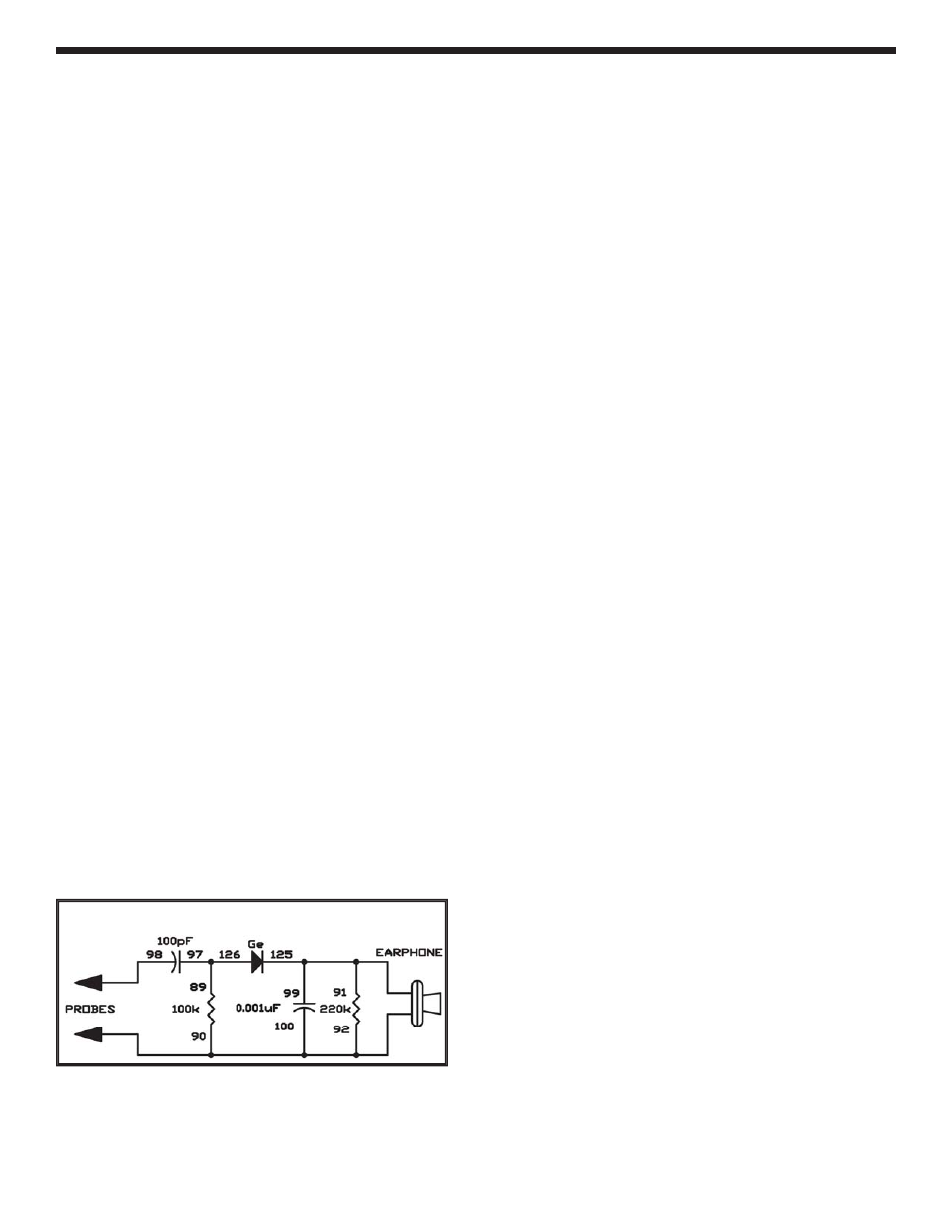
EXPERIMENT #118: RF SIGNAL TRACER
Schematic
Wiring Sequence:
89-97-126
90-92-100-EARPHONE-PROBES
125-99-91-EARPHONE
98-PROBES
- Upgrade Kit SC100 to SC300 (76 pages)
- Snap Circuits Jr.® Educational 100 Exp. (48 pages)
- Upgrade Kit SC300 to SC500 (64 pages)
- Snap Rover ® (24 pages)
- XP&trade (64 pages)
- Snap Circuits LIGHT ® (84 pages)
- Snap Circuits Extreme® Educational 750 Exp. (88 pages)
- Projects PC1-PC73 (60 pages)
- Electronics 202 (132 pages)
- Snaptricity® (92 pages)
- Upgrade Kit SCROV10 to SCROV50 (48 pages)
- Snap Circuits Green ® (80 pages)
- C Adapter for Snap Circuits® (2 pages)
- Motion Detector Kit (20 pages)
- Digital Roulette Kit (16 pages)
- FM Wireless Microphone Kit (12 pages)
- AM Radio Kit (32 pages)
- AM Radio Kit (36 pages)
- AM/FM Radio Kit (64 pages)
- Circuit Maker Skill Builder 125 (64 pages)
- Circuit Maker Sound Plus 200 (80 pages)
- Understanding Logic Gates (16 pages)
- Understanding Logic Gates and Circuits (42 pages)
- Tumbling Robot (12 pages)
- Solar Energy (16 pages)
- C2D Scope (16 pages)
- 288x Astrolon Telescope with Aluminum Tripod (1 page)
- Simulated Frog Dissection Kit (1 page)
- Talking Galaxy Planetarium with Night Light (1 page)
- Night’n Day® (10 pages)
- Radio Controlled Black Widow (1 page)
- Handheld Microscope (2 pages)
- Water Filtration Kit (8 pages)
- 6-in-1 Solar Kit (18 pages)
- Microscope Set in Carrying Case (1 page)
- Mobile 20 Telescope (1 page)
- Mechanical Drum (20 pages)
- Aerial Screw (20 pages)
- Swing Bridge (20 pages)
- Printing Press (24 pages)
- MultiBarrel Cannon (20 pages)
- Armored Car (24 pages)
- Paddleboat (20 pages)
- SelfPropelled Cart (20 pages)
- Catapult (24 pages)