Experiment #53: dark shooting, Experiment #72: non-inverting dual supply op amp – Elenco 130-in-1 Electronics Playground User Manual
Page 70
-70-
Think you have good night vision? This experiment is
a game that lets you find out how well you can see in
the dark. In a completely dark room, it tests your aim!
Once you have completed this project, put it in as
dark of a room as possible. Slide the switch to
position A and modify the control in a counter-
clockwise direction until LED 1 and LED 3 light. Now
it is time to test your ability.
For this game your “gun” is a typical flashlight. With
a beam of light you use your flashlight to “shoot” the
kit. If your aim is correct, you’ll hit the CdS cell to light
LED 2 and turn off LED 1 and LED 3. Then turn off
your flashlight and wait until LED 2 goes off before
you try your next shot.
Start off trying to hit the CdS cell from around five
feet or so. You aim will improve as you increase your
distance. Once you get really good, you can try
hitting the CdS cell simply by switching your flashlight
on and off rather than using a continuous stream of
light.
You may have to modify the control knob very
carefully to have LED 2 come on when light strikes
the CdS cell. For the best results, use a sharply
focused flashlight (not a fluorescent lamp or other
light) and be sure you have the kit in a completely
dark room. Once you’ve found the best setting, keep
it there so you can use it again. Don’t change it until
you want to stop using the “shot in the dark” game.
Have fun and good luck
☺
Notes:
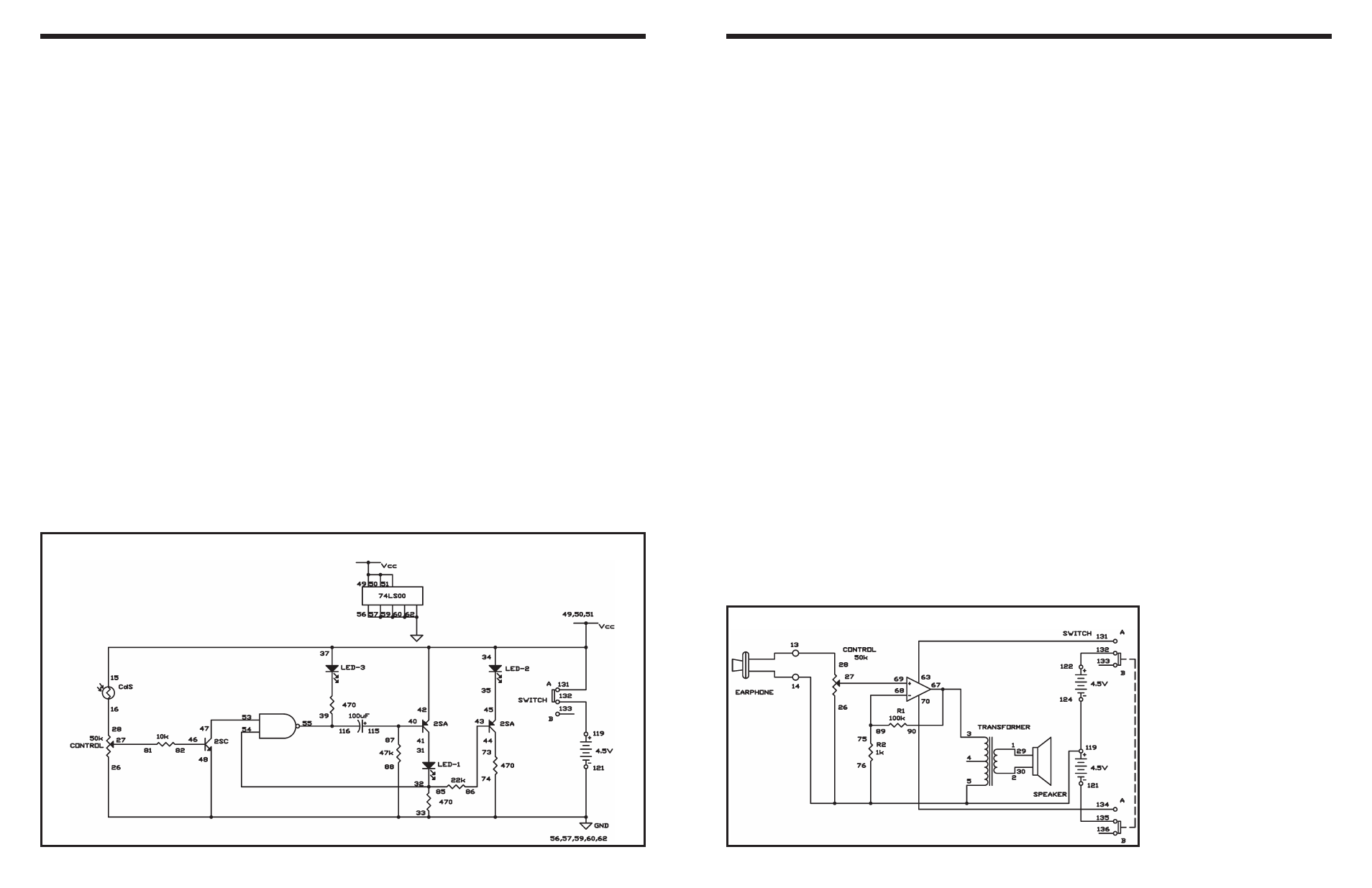
EXPERIMENT #53: DARK SHOOTING
Wiring Sequence:
o 15-34-49-50-51-37-42-131
o 16-28
o 48-121-26-88-74-62-60-59-57-56-33
o 27-81
o 31-41
o 32-54-85
o 35-45
o 73-44
o 39-55-116
o 40-115-87
o 43-86
o 46-82
o 47-53
o 119-132
Schematic
-91-
In this experiment, you will make a microphone
amplifier, using the operational amplifier (op amp) as
a non-inverting amplifier with two power sources. The
earphone acts as a microphone.
Begin by sliding the switch to position B and finishing
the wiring for the circuit. When your wiring is ready,
set the switch to position A to turn on the power. Now
rotate the control fully clockwise, and lightly tap your
“microphone” – the earphone. The tapping sound is
heard through the speaker.
The earphone is a better microphone if you remove
the end that you put in your ear, by turning it counter-
clockwise to unscrew it. To adjust the volume, turn
the control.
As you can observe in the schematic, the operational
amplifier uses two power sources: 4.5V for the circuit
and 9V for the IC. The signal from the earphone is
connected to the operational amplifier’s non-inverting
input through the control. The input is amplified, and
the output is applied to the transformer. The gain
through the amplifier is about 100, determined by the
ratio R1/R2 (100k
Ω / 1kΩ = 100).
Notes:
EXPERIMENT #72: NON-INVERTING DUAL SUPPLY OP AMP
Wiring Sequence:
o 1-29
o 2-30
o 3-67-90
o 27-69
o 63-131
o 68-89-75
o 70-134
o 121-135
o 122-132
o 124-119-26-76-5-14-EARPHONE
o 28-13-EARPHONE
Schematic