Experiment #4: grandfather clock, Experiment #124: water level buzzer – Elenco 130-in-1 Electronics Playground User Manual
Page 15
-146-
-15-
Does your home lack a grandfather clock? Well not
any longer, with this experiment you will make your
own electronic grandfather clock.
This circuit will produce clicks at approximately one-
second intervals. The sound and timing together
might remind you of an old grandfather clock. If you
would like for it to go faster or slower then you can
change out the 100k
Ω resistor.
The steady ticking can put animals (and people) into
a sleepy state of mind. If you have ever traveled on a
train, you remember how sleepy you get from
hearing the clicking sound of the wheels.
Ever scare a clock out of ticking? Shout directly into
the speaker. You can briefly stop the clock! The
speaker acts like a microphone as well. The sound
of your voice vibrates the speaker and disturbs the
electrical balance of the circuit, briefly.
Notes:
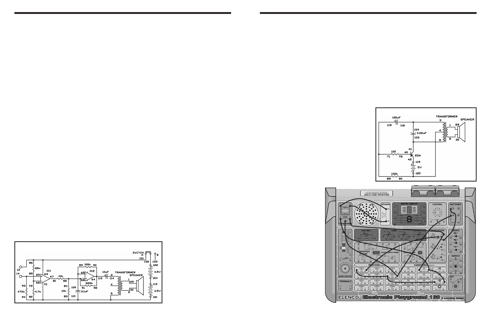
EXPERIMENT #4: GRANDFATHER CLOCK
Wiring Sequence:
o 1-29
o 2-30
o 3-104-116
o 4-90-120
o 5-41-103
o 40-72
o 42-119
o 71-89-115
Schematic
You can use the operational amplifier as a
comparator for detecting changes in voltage. In this
experiment, you are going to use this comparator
function to make a water buzzer that sounds when
the wire ends come into contact with water.
Slide the switch to position B, build the circuit, and
then slide the switch to position A to turn on the
circuit. You should not hear any sound from the
speaker. Now connect the two output terminals with
a wire, and you hear a sound from the speaker.
Touch the two output terminals with your fingers. If
the speaker makes a sound again, the electricity is
flowing through your body because the wire lead is
in contact with sweat.
This experiment uses two operational amplifiers. IC
1 works as a comparator. The IC’s negative (–) input
terminal has a reference voltage of about 1.6V. When
a voltage exceeding 1.6V is applied to the positive
(+) input terminal, the output of the comparator
allows IC 2 to work as an astable multivibrator.
Notes:
EXPERIMENT #124: WATER LEVEL BUZZER
Wiring Sequence:
o 1-29
o 2-30
o 3-114
o 5-83-80-94-70-110-121
o 13-86-63-131
o 14-93-69
o 65-89-109
o 66-82-84-91
o 64-90-92-113
o 67-81
o 68-79-85
o 119-124
Schematic