Experiment #23: led display basics, Experiment #104 dc-dc converter – Elenco 130-in-1 Electronics Playground User Manual
Page 37
-124-
-37-
By using the LED display you will see the effect of
electrical signals. An LED is similar to a normal diode
except when current flows through it, it emits light.
One example of the LED display is a power indicator
on your DVD player or your radio that tells you the
power is on.
A seven-segment LED display can show the
numbers 0 through 9 for reading information on a
calculator. Seven is the minimum number of
segments (separate lines that can be each lighted)
that are necessary to clearly distinguish all ten digits.
Two conditions that you must always observe for the
proper LED operation are:
1. Polarity correctness (+ and – LED connections)
2. Proper current flow
LEDs can burn out due to reverse polarity if the
voltage is more than about 4 volts, or if the current is
not limited to a safe value. When the polarity is
reversed the LED will not light.
Series resistors (permanently wired to your kit) are
used with the LED display to keep the current flow at
a proper level. Current flows through these resistors
and the LED to terminal 25, providing a
comparatively constant voltage (approx. 1.7 volts) to
the LED. To make the current flow through the LED
display we need voltages above this value. The
series resistors set how much current flows from the
batteries through the LED.
Now it is time for you to learn about the common-
cathode seven-segment LED digital display. Seven
LED display segments use one contract point –
terminal 25 – as a common negative electrode in a
common- cathode.
To allow current to flow through an LED must have
both (+) and (–) connections. The anode is the
positive side and the cathode is the negative side. In
this kit the LED display is a common cathode type.
You connect any anode segment terminals as
required, to the battery’s positive side and connect
the common cathode segment terminal (terminal 25)
to the negative side of the battery.
LEDs operate tremendously fast. An LED can turn
off and on hundreds of times per each second; so
fast that you won’t even see it blink. There is no warm
up time or large amount of heat produced unlike an
incandescent lamp.
Do the following experiment to experience how fast
the LED operates.
1. Do not close the key but hook up the circuit.
2. Decrease the light in the room to a low level so
that you are able to see the LED light emission
easily.
3. Close the key but only for less than a second.
You will notice that the display goes quickly off and
on. Hold the platform steady but glance quickly at the
LED as you quickly tap the key. It will appear that the
display goes on and off. What occurs in the
persistence of the human eye is much longer than
the LED’s time but without the use of special
instruments this gets the point across.
Notes:
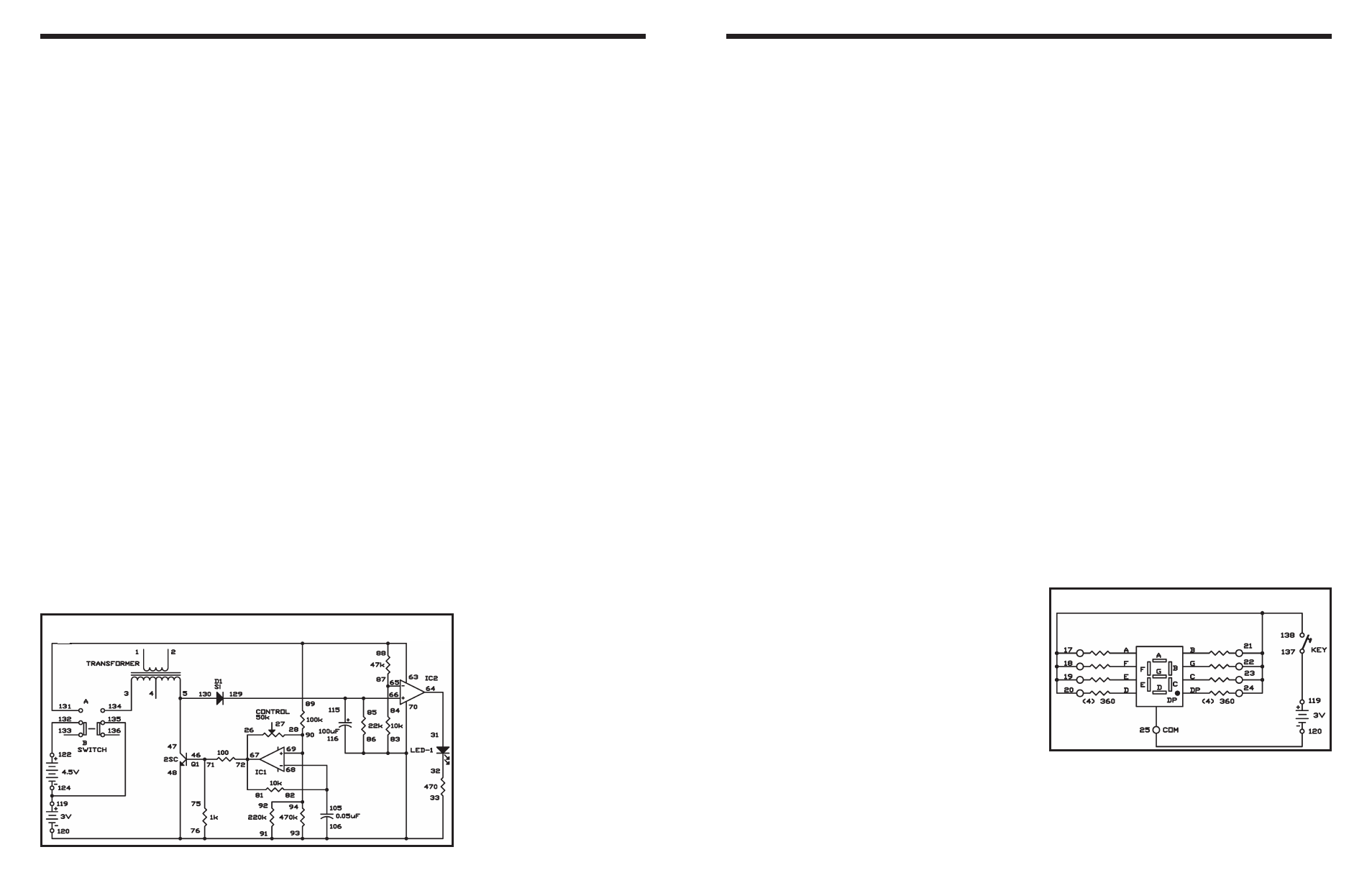
EXPERIMENT #23: LED DISPLAY BASICS
Wiring Sequence:
o 17-18-19-20-21-22-23-24-138
o 25-120
o 119-137
Schematic
Here’s a DC-DC converter circuit; it can make 5VDC
from 3VDC. Assemble the experiment, set the switch
to position A, and see how this circuit works.
The schematic shows how it works. IC 1 is an
oscillator; its output controls transistor Q1. Self-
induction of the transformer coil generates a high
voltage current. Diode D1 rectifies this voltage and
passes on a high DC voltage current. IC 2 is a
comparator that examines the voltage. When the
input voltage to IC 2 is more than 5V, the LED lights.
How does turning the control affect the circuit? The
control is used as a fixed resistor of 50k
Ω, so turning
the control has no effect.
Notes:
EXPERIMENT #104 DC-DC CONVERTER
Wiring Sequence:
o 3-134
o 5-47-130
o 26-67-72-81
o 28-69-90-92-94
o 31-64
o 33-76-83-86-93-91-70-106-116-48-120
o 46-71-75
o 89-88-63-131
o 84-87-65
o 85-66-115-129
o 82-68-105
o 119-124-135
o 122-132
Schematic