Experiment #40: “and” enable circuit using ttl, Experiment #86: buzzin’ with the op amp – Elenco 130-in-1 Electronics Playground User Manual
Page 56
-56-
Setting the switch to B blocks the channel from the
LED 1 to the LED 2 However, when you set the
switch to A, you will find that LED lights and turns off
at the same time as LED 1. The two NAND gates
produce an AND gate.
In this circuit the LED 1 is known as the data input.
The output is the LED 2. Frequently these terms are
used with enable circuits. They will show up from time
to time when we talk about digital circuitry.
As you may have suspected by now, we can use
digital circuits to perform enable functions. Are you
able to figure out how? Make sure to keep the notes
of your findings especially if you are able to figure out
how to use an OR gate in an enable circuit.
Notes:
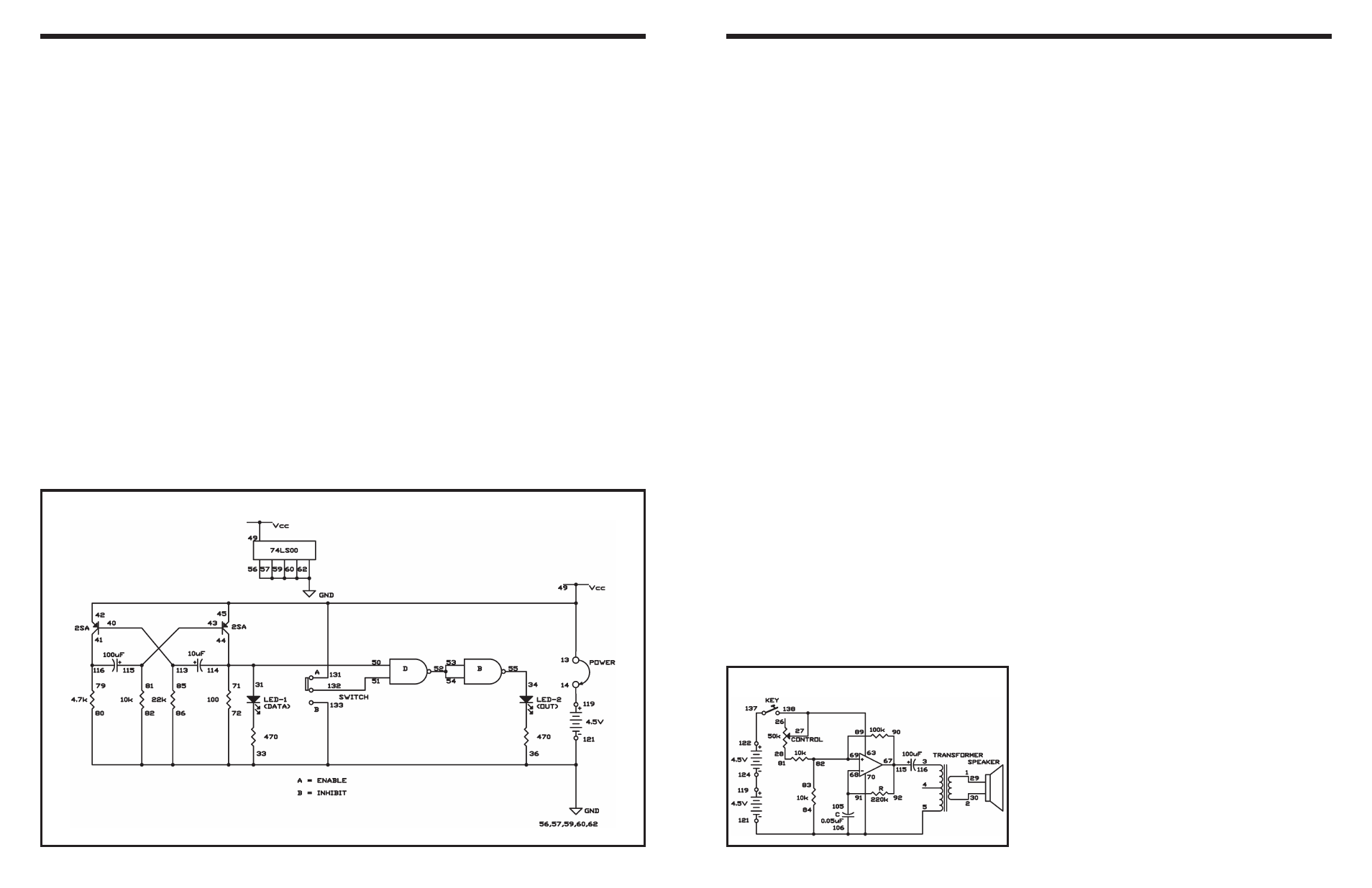
EXPERIMENT #40: “AND” ENABLE CIRCUIT USING TTL
Wiring Sequence:
o 13-49-42-45-131
o 14-119
o 71-50-31-44-114
o 86-82-80-72-56-57-59-60-62-33-36-121-133
o 34-55
o 40-113-85
o 41-116-79
o 43-115-81
o 51-132
o 52-53-54
o 13-14 (POWER)
Schematic
-105-
The operational amplifier (op amp) works well as an
oscillator. In this experiment, you will build an electric
buzzer that makes a continuous beep. By rotating the
control you can change the tone of this buzzer.
When you finish the wiring, set the control to the 12
o’clock position and press the key. From the speaker
you hear a continuous beep. Turn the control as you
press the key; the tone of the buzzer changes.
The electronic buzzer only makes a beep, but it can
be used for many different purposes, as you’ll see
later.
This circuit is an astable multivibrator working as an
oscillator to produce a square wave signal for the
speaker. Adjusting the control changes the
frequency, so the tone of the sound is different. The
frequency is determined by the resistors and
capacitor connected to the input terminals of the
operational amplifier. Try changing the capacitor to
0.02
μF or 0.1μF and see how the tone changes.
Notes:
EXPERIMENT #86: BUZZIN’ WITH THE OP AMP
Schematic
Wiring Sequence:
o 1-29
o 2-30
o 3-116
o 5-84-70-106-121
o 63-27-138
o 28-81
o 67-90-92-115
o 91-68-105
o 69-82-83-89
o 119-124
o 122-137