Experiment #57: another led buzzin, Experiment #69: electronic organ oscillator – Elenco 130-in-1 Electronics Playground User Manual
Page 74
-74-
Carefully compare the schematic for this experiment
with the schematic for the last experiment. While they
are similar in many ways, but there’s a critical
difference. Can you find what it is? Can you tell how
the operation will be different?
Attach the earphone to Terminals 13 and 14 and set
the switch to position A. You will hear nothing in the
earphone but you should find that LED 1 lights up.
You will hear a sound in the earphone once LED 1
turns off.
Try to decipher why this happens. Examine the
schematic and when you think you have the answer,
read on to check your guess.
When the output of the NAND multivibrator is 0, the
voltage at the junction of springs 42-58-33 is low. This
allows current to flow through LED 1, but the
transistor multivibrator won’t work because there is
no voltage to its left transistor. When the output of the
NAND multivibrator is 1, the voltage at the springs
42-58-33 junction is high. This prevents current from
flowing through LED 1, but the transistor multivibrator
now works because there is voltage to its left
transistor, and this multivibrator controls the
earphone sound.
Notes:
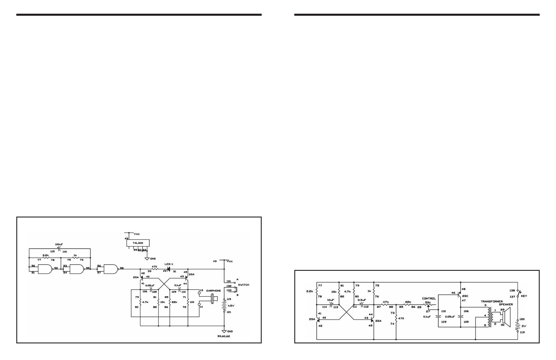
EXPERIMENT #57: ANOTHER LED BUZZIN’
Wiring Sequence:
o 131-45-31-49
o 116-76-56-57-55
o 40-109-85
o 42-58-33
o 43-105-81
o 50-51-77-115
o 52-53-54-75-78
o 72-59-60-62-80-82-86-121
o 119-132
o 44-110-71-13-EARPHONE
o 41-106-79-14-EARPHONE
Schematic
-87-
This circuit has a multivibrator connected to a pulse
type oscillator. Rather than turning the oscillator
completely on and off, the multivibrator provides a
tremolo effect (a wavering tone).
After you build the circuit, use the control to vary the
base current supplied to the NPN transistor. This
changes the charge/discharge rate of the 0.1
μF and
0.05
μF capacitors, as well the frequency of the pulse
oscillator.
The key works to turn the whole circuit on and off.
You can substitute it with the slide switch. By
changing the 10
μF and 3.3μF capacitor values, you
can change the tonal range.
Try using the switch or the key to add additional
components to the circuit (like an extra capacitor in
parallel with the 10
μF or 3.3μF), so you can alter
from one tonal range to another, quickly. These
changes will make a more complete organ from this
experiment. Be sure to make notes on what you do.
Notes:
EXPERIMENT #69: ELECTRONIC ORGAN OSCILLATOR
Wiring Sequence:
o 1-29
o 2-30
o 3-47-106
o 4-74-45-42-119
o 5-105-109
o 27-46-110
o 28-86
o 40-111-80
o 41-114-78
o 43-113-82
o 44-112-87-76
o 77-75-81-79-48-138
o 73-85-88
o 120-137
Schematic