Experiment #103: light-controlled sound – Elenco 130-in-1 Electronics Playground User Manual
Page 38
-123-
-38-
Wire the circuit as shown to connect the 3V supply
to the LED segments and the decimal point (Dp).
What numbers and letters do you see displayed?
In this experiment you can make some voltage
measurements using a Voltage/Ohm Meter (VOM) if
you have one. Connect the VOM as directed by its
instructions. Skip these measurements if you do not
have a VOM.
With this low battery voltage, you can reverse the
polarity of the circuit by reversing the connections to
the battery. (Changes to make are: change 25-120
and 119-WIRE, 25-119 and 120-WIRE.) Record your
results. After you note your results, reconnect the
battery with the correct polarity. Measure the LED
voltages between terminal 25 and each separate
terminal (17 through 24) using a VOM if you have
one. Change the battery connections to 25-124, 121-
122, and 119-WIRE to temporarily change the 9V
supply. Next, make the same measurements. What
amount is the LED voltage increased by, from using
this three-time increase from the battery? (A normal
increase is 0.25V)
Next, try measuring the voltage in each resistor
attached to one of the LED segments. All of the
resistors are 360
Ω. The LED current is in milliamps
(one-thousandths of an ampere) is calculated by
dividing the voltage by 360
Ω. The LED segment
currents are approximately ____ milliamperes (mA)
with the 3V supply (3mA typically), and ____ mA with
the 9V supply.
Make a chart of the connections required to display
0 through 9 on the display in the space below.
Notes:
EXPERIMENT #24: DIGITAL DISPLAY CIRCUIT FOR THE SEVEN-SEGMENT LED
Wiring Sequence:
o 25-120
o 119-WIRE
or
o 25-120
o 119-(17, 18, 19, 20, 21, 22, or 23)
Schematic
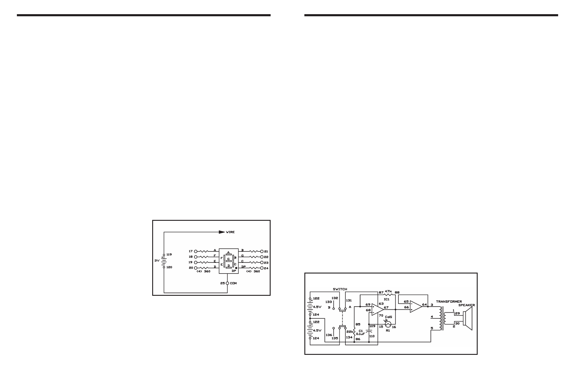
This circuit changes the intervals between each
sound according to the amount of light falling on the
CdS cell. The sound changes continuously as you
alter the light intensity.
Build the circuit, and set the switch to position A to
turn on the power. The speaker makes a sound. To
change the sound, move your hand over the CdS.
You can calculate the approximate value of the
frequency of the signal by using the equation 1/2 x
C1 x R1. However, R1, in this project, is the CdS and
is not constant. By changing C1 you can change the
value of the output frequency. In this experiment,
another operational amplifier is used as a buffer, so
the light-controlled sound part of the circuit is not
affected by the speaker sound.
Notes:
EXPERIMENT #103: LIGHT-CONTROLLED SOUND
Wiring Sequence:
o 1-29
o 2-30
o 3-64-65
o 5-86-110-119-124
o 15-68-109
o 16-66-67-88
o 63-131
o 69-87-85
o 70-134
o 121-135
o 122-132
Schematic