Experiment #45: “or” enable circuit using ttl, Experiment #81: single flash light – Elenco 130-in-1 Electronics Playground User Manual
Page 61
-61-
Have you figured out how to make an enable circuit
using an OR gate? Well, if the answer is yes, then
this is your chance to compare you design to our OR
enable circuit.
As done in projects 35 and 36, the multivibrator
provides the input to the OR gate in this circuit. You
can observe the output of the OR gate when you
view LED 1—it flashes on and off corresponding to
the output of the multivibrator. Can you tell what
occurs when the multivibrator’s input is applied to the
OR gate by viewing the schematic? Give it a try
before building the project.
Before completing this circuit, set the switch to A.
Connect terminals 13 and 14 to turn the power on
once you have finished the wiring. What does LED 1
do? What does LED 2 do? Set the switch to B. What
occurs to LED 1 and LED 2 now?
We can simplify the circuit by stating that setting the
switch to A blocks the flow of the data from LED 1 to
LED 2. We call this inhibit status. An enable status
occurs when the switch is at B; then data can flow
from LED 1 to LED 2.
Notes:
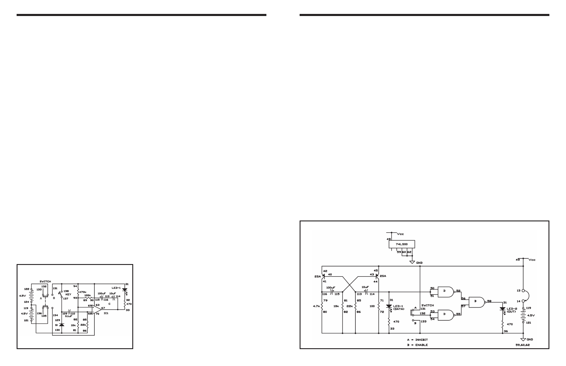
EXPERIMENT #45: “OR” ENABLE CIRCUIT USING TTL
Wiring Sequence:
o 13-49-42-45-131
o 14-119
o 71-50-51-31-44-114
o 86-82-80-72-59-60-62-33-36-121-133
o 34-58
o 40-113-85
o 41-116-79
o 43-115-81
o 52-56
o 53-54-132
o 55-57
o 13-14 (POWER)
Schematic
-100-
You’ve built many circuits using the operational
amplifier, but there are lots of other ways to use this
handy IC. One of them is the single flash
multivibrator. With this multivibrator, you can make
the LED stay on for a preset amount of time when
the key is pressed - a single flash light.
Slide the switch to position B and construct the
circuit. Turn the power on by sliding the switch to
position A. The LED lights, but quickly turns off. Now,
press the key and observe what happens. The LED
lights and stays on for 2 to 3 seconds and then turns
off.
By using different values for C You can change the
amount of time the LED is on. Change the value of
C from 10
μF to 100μF and see what occurs to the
LED. It stays on longer.
Notes:
EXPERIMENT #81: SINGLE FLASH LIGHT
Schematic
Wiring Sequence:
o 31-63-94-131-138
o 33-67-114
o 85-68-110
o 69-82-89-93
o 70-134
o 81-86-130-124-119
o 90-115
o 109-137-129
o 113-116
o 121-135
o 122-132